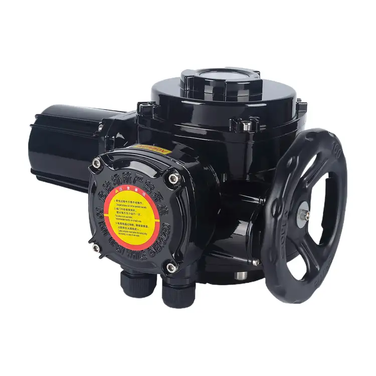
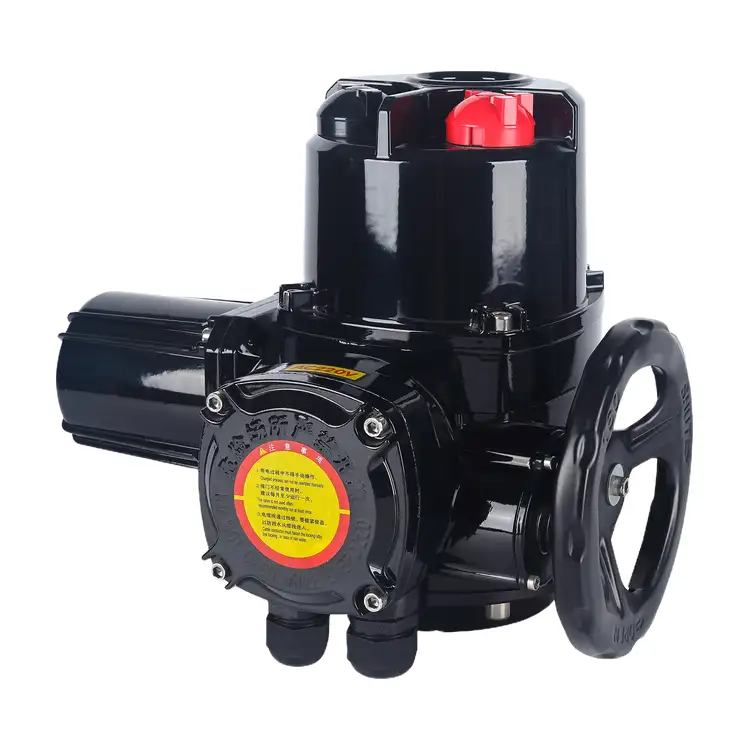
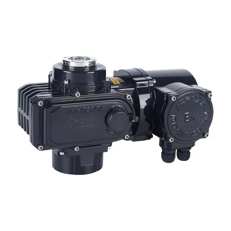
QB Series Electric Valve Actuator
The QB Series Electric Valve Actuator from Liangfa is designed for 90° rotary valves in industrial applications requiring reliable operation and explosion protection. With output torque ranging from 125 to 4000 N·m, it supports butterfly valves, ball valves, plug valves, and air dampers. Available in basic on-off, integrated control, and 4–20 mA modulating configurations, it offers flexible integration with PLC and DCS systems.
The QB Series Electric Valve Actuator is designed for 90° rotary valve automation in industrial environments where explosion protection and dependable operation are essential. At Liangfa, we offer this series for butterfly valves, ball valves, plug valves, and air dampers, with output torque ranging from 125 to 4000 N·m.
Options include basic on-off control, an integrated control unit, and 4–20 mA modulating control for PLC or DCS systems. With an Ex d IIB T4 design, standard IP65 protection, and dual travel and torque protection, our actuators support valve automation in petrochemical facilities, oil and gas handling systems, and other suitable hazardous-area applications.
Check Hazardous-Area Requirements First
Before selecting an actuator for a potentially explosive atmosphere, we recommend confirming the gas group, temperature class, hazardous-area classification, and applicable certification requirements. These factors determine whether the standard configuration is suitable or a customized version is needed.
Explosion Protection
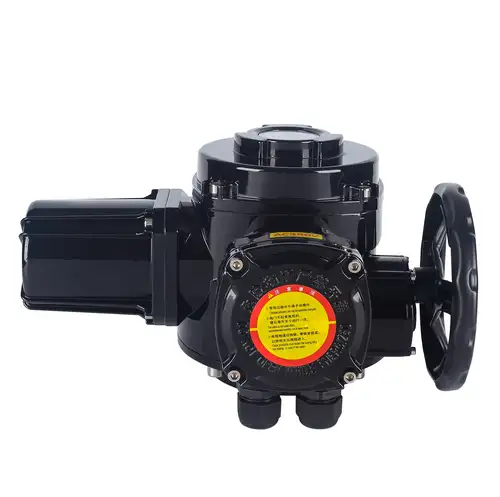
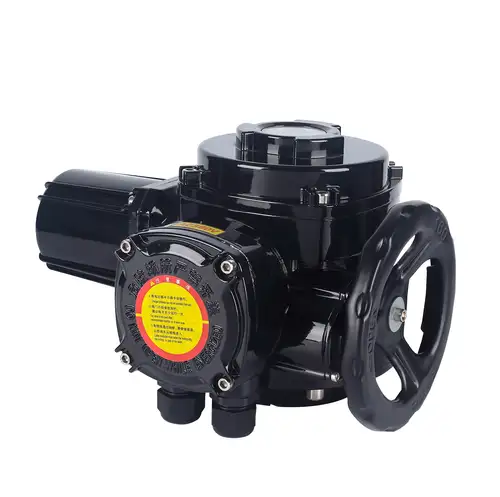
The QB series uses an Ex d IIB T4 flameproof design intended for compatible applications in Zone 1 and Zone 2 hazardous gas environments involving Group IIA and IIB gases within temperature classes T1–T4. Its flameproof enclosure is designed to contain internal ignition sources and help prevent ignition of the surrounding atmosphere when installed and maintained according to the applicable requirements.
For applications involving Group IIC gases, such as hydrogen, a suitable Ex d IIC version must be specifically confirmed. Surface coal-mine applications require the appropriate mine-specific flameproof configuration. The standard industrial version must not be assumed suitable for underground mine working faces.
For each project, we recommend confirming the actual product marking, certificate scope, cable-entry requirements, and installation conditions before ordering. The enclosure must remain properly sealed and grounded, and its flameproof mating surfaces must not be damaged.
Ingress Protection and Ambient Conditions
Standard enclosure protection is IP65, with IP67 available as an option. IP67 may suit certain short-term immersion conditions, but it does not mean the QB Series Electric Valve Actuator can remain submerged continuously. For outdoor installations, we recommend suitable rain and sun protection where direct exposure is expected.
The standard ambient operating range is -20°C to +60°C. Customized low-temperature versions can be discussed for applications down to -40°C, while higher-temperature versions may be available for specific projects. The required configuration and maximum permitted temperature should be confirmed before use. If heat from the valve body could reach the actuator, suitable thermal isolation is necessary.
Match Torque to the Actual Valve
Selecting an actuator only by valve diameter can lead to unreliable operation. The required torque depends on the valve design, differential pressure, medium, sealing arrangement, deposits, and operating frequency. We recommend using the maximum breakaway torque supplied by the valve manufacturer as the starting point.
A practical selection method is:
Required actuator torque = maximum valve breakaway torque × application safety factor.
| Operating Condition | Suggested Safety Factor | Typical Consideration |
|---|---|---|
| Clean medium and normal on-off service | 1.3 | Clean water and conventional pipeline isolation |
| Dirty medium or scaling risk | 1.5 | Sewage, impurity-bearing media, or valves left idle for long periods |
| Frequent intermittent modulation | 1.5–2.0 | Flow-control loops requiring repeated positioning |
| High differential pressure, high temperature, or slurry | At least 2.0 | Conditions that may increase resistance or cause valve sticking |
These factors are preliminary selection guidance, not a substitute for the valve manufacturer's torque data or an engineering review. Insufficient torque may prevent the valve from completing its stroke, while excessive torque can damage the valve stem, coupling, or internal components.
Available Torque Ratings
The QB family includes several torque ratings, with the model designation indicating the nominal torque range according to the supplied naming convention. For example, QB100 corresponds to 1000 N·m. We recommend confirming the exact rated torque, output speed, flange size, and shaft connection for the selected model before finalizing an order.
| Model Example | Nominal Output Torque | Selection Note |
|---|---|---|
| QB10 | 100 N·m according to the model convention | Confirm the model's rated output and available configuration |
| QB20 / QB30 / QB40 | 200 / 300 / 400 N·m | Match to the valve's measured or manufacturer-provided torque |
| QB60 / QB100 | 600 / 1000 N·m | Check operating pressure, medium, and required safety factor |
| QB200 / QB300 / QB400 | 2000 / 3000 / 4000 N·m | Verify mounting interface and the complete valve assembly requirements |
The model examples above follow the source naming convention. Please confirm the current model list and available specifications with us before purchase.
Choose the Right Control Arrangement
The control configuration affects wiring, commissioning, and how the actuator interacts with the plant control system. We supply different arrangements to suit projects that use a centralized control cabinet, local push-button operation, or analog process regulation.
Basic On-Off Type
The basic type does not include a built-in control unit and requires a separate external control cabinet. It is suitable when the plant already has a centralized motor-control arrangement or when the project requires the control equipment to be installed separately.
Integrated Z Type
The QB-Z version incorporates a control module for local push-button operation and remote discrete control signals. Passive contacts can provide fully open and fully closed position feedback. This arrangement reduces the need for a separate external control cabinet and simplifies field wiring for two-position valve service.
TJ Modulating Type
For process applications that require intermediate valve positions, we offer the QB-TJ-Z configuration with a built-in servo module. It accepts a 4–20 mA command signal and provides 4–20 mA valve-position feedback, allowing integration with compatible PLC and DCS systems.
The supplied specifications state a positioning accuracy of approximately ±2.5% for the modulating version. Actual control performance depends on the selected model, commissioning, valve characteristics, and operating conditions. A dedicated modulating actuator should be used for regulation; a standard on-off model should not be substituted for frequent positioning duty.
| Configuration | Control Arrangement | Suitable Use |
|---|---|---|
| Basic type | External control cabinet | Projects with centralized control equipment |
| QB-Z integrated type | Local controls, remote discrete signals, open/closed feedback | Remote isolation and two-position valve control |
| QB-TJ-Z modulating type | 4–20 mA input and position feedback | Intermittent flow or pressure regulation |
Set the Required Valve Travel Time
Output speed determines how long the actuator takes to complete a 90° stroke. The appropriate speed depends on valve size, process response, and whether rapid shut-off or a more gradual movement is required.
| Output Speed | Approximate 90° Stroke Time | Typical Consideration |
|---|---|---|
| 0.5 r/min | 30 seconds | Large valves or applications where slower movement is preferred |
| 1 r/min | 15 seconds | General-purpose quarter-turn operation |
| 2 r/min | 7.5 seconds | Applications requiring faster movement, subject to valve limits |
These stroke times are approximate reference values. Actual travel time can vary with the model and valve assembly. For water pipelines and other systems sensitive to pressure surges, we recommend checking whether a slower stroke is required to reduce water-hammer risk.
The standard actuator is designed for short-time duty, with a typical maximum continuous energization period of 10 minutes. An extended 30-minute-duty configuration may be discussed for projects that require it. For repeated regulation, select the dedicated modulating version and confirm the duty rating against the actual control cycle.
Mechanical Fit and Protection Features
Even when the torque and control mode are correct, the QB Series Electric Valve Actuator must match the valve's mechanical interface. Before production or shipment, we recommend checking the mounting flange, drive bore, shaft dimensions, and the direction of valve travel.
ISO 5211 Mounting Interface
Available flange interfaces include F07, F10, F12, and F14, depending on the selected model. The actuator flange must match the valve's top flange. Round or square valve shafts must fit the output drive correctly; an appropriate adapter bushing may be required where dimensions differ.
Travel and Torque Protection
A cam-operated travel-limit mechanism stops movement at the configured end positions. A separate torque-protection mechanism helps prevent damage when a valve becomes jammed or requires more torque than expected. These functions are intended to reduce the risk of over-travel and overload, but correct sizing and limit adjustment remain essential.
Manual Operation During Power Loss
The semi-automatic manual-electric changeover mechanism allows an operator to move the valve manually when electrical power is unavailable. When returning to electric operation, the mechanism resets automatically according to the design, so a separate manual-lever reset is not required.
The actuator uses a worm-gear reduction mechanism with self-locking characteristics to help maintain valve position after power is removed. In installations exposed to persistent pipeline vibration, mounting bolts, supports, and wiring connections should still be inspected periodically.
Applications in Industrial Facilities
We recommend matching the actuator version to the site's actual hazard classification, valve type, and process requirements. Typical application areas include:
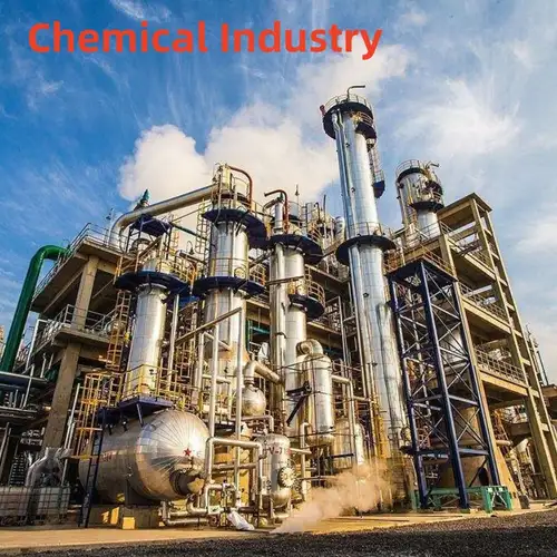
Petrochemical and Chemical Processing
Suitable configurations can operate compatible quarter-turn valves on process pipelines, solvent lines, and other systems in appropriately classified hazardous areas. The selected explosion-protection marking must match the gases and conditions present at the installation site.
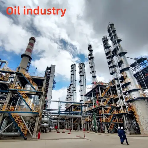
Oil and Gas Storage
The QB Series Electric Valve Actuator can be used for remote valve isolation and tank-farm inlet or outlet control where the valve interface and hazardous-area requirements are satisfied. Emergency shut-off functions must be assessed as part of the complete control and safety system.
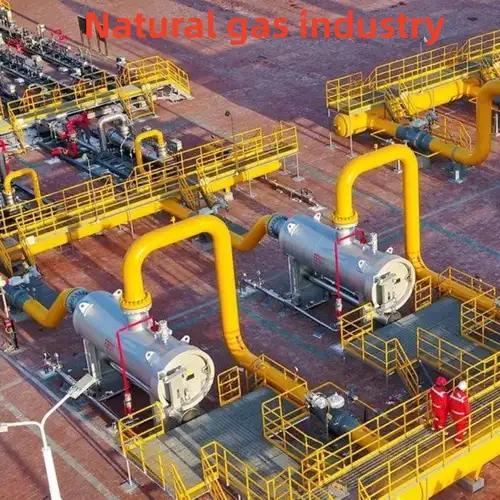
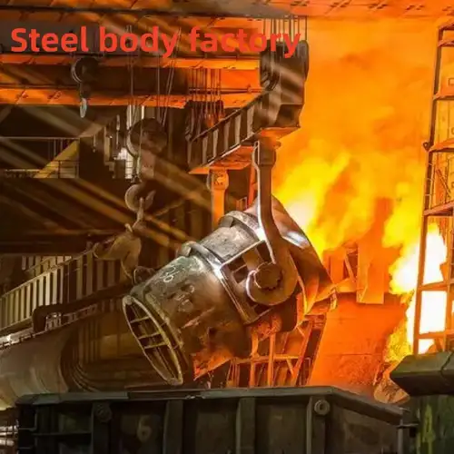
Gas Supply and Coal-Chemical Plants
For gas transmission, pressure-regulating stations, and coal-chemical process systems, the actuator can provide two-position operation or modulating control when the correct configuration is selected. Applications involving hydrogen or other Group IIC gases require specific confirmation of the explosion-protection version.
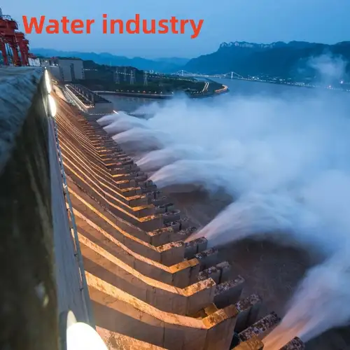
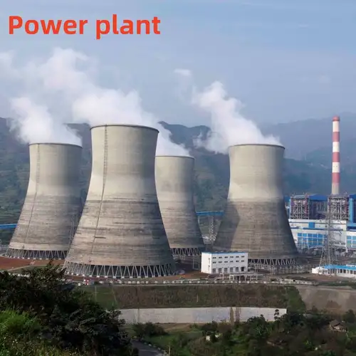
Power and Industrial Water Treatment
Compatible configurations may operate flue-gas dampers, process-water valves, and chemical wastewater valves in suitable industrial environments. For wastewater containing flammable vapors, the area classification and gas characteristics must be assessed before choosing the actuator.
The QB series is intended for 0–90° partial-turn applications. It is not designed to directly operate multi-turn valves such as gate valves or globe valves.
Manufacturing and Delivery Support
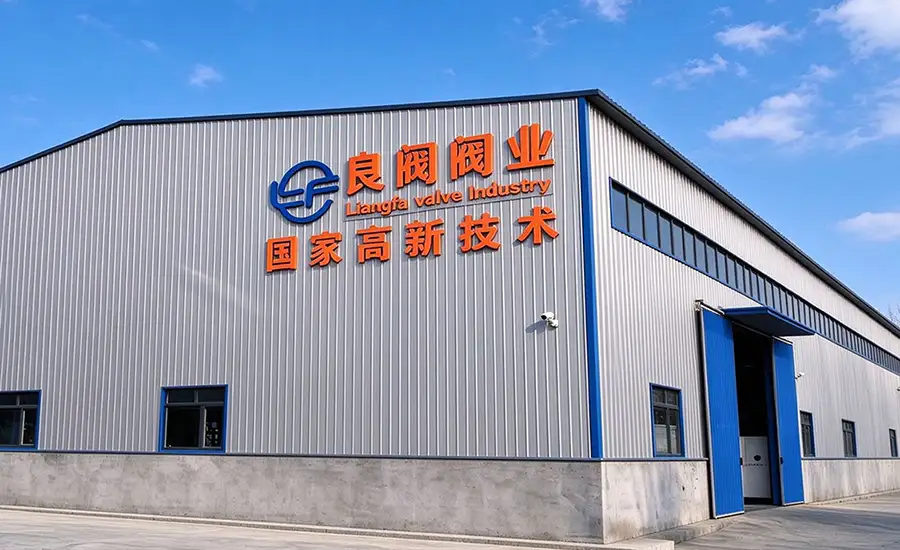
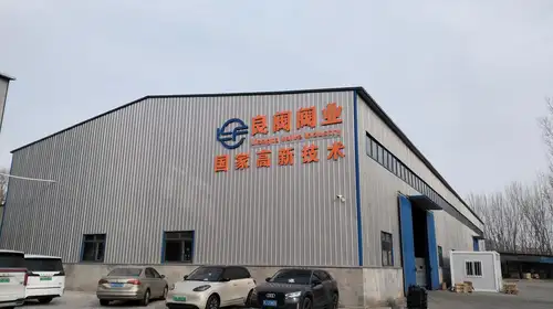
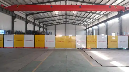
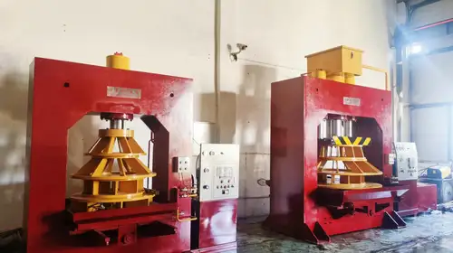
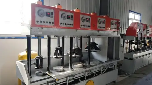
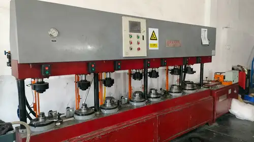
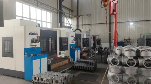
At Liangfa, we support customers with model selection, configuration confirmation, production coordination, and technical assistance. As a high-tech enterprise, we focus on practical actuator solutions for industrial valve automation. Our high-tech enterprise certificate reflects the company's recognized enterprise status; it should not be interpreted as an individual product certification or as a substitute for the required explosion-proof certificate.
Before shipment, customers can discuss the required model, control configuration, power supply, mounting interface, and inspection documentation with our team. For hazardous-area projects, the product marking and certificate scope should be checked against the project specification before installation.
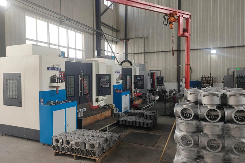
Factory and Production


Export Packing
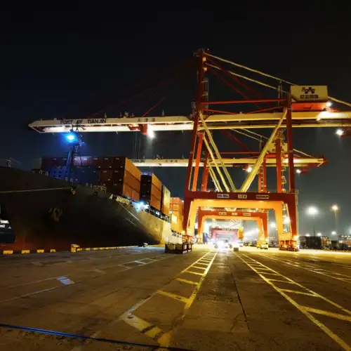
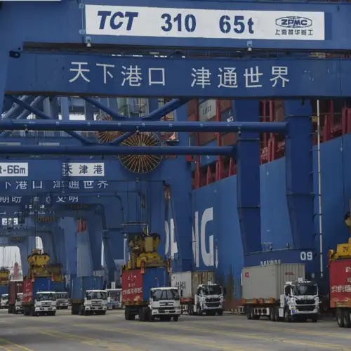
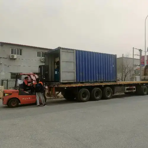
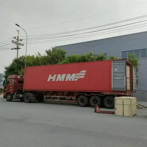
We support sea and land transport and prepare export documentation according to the order requirements. Packaging and shipping arrangements can be confirmed according to the destination, order quantity, and transport method.
Technical Assistance and After-Sales Service
We provide pre-sales assistance for torque selection, control-mode configuration, power-supply requirements, and mounting compatibility. Customers can also request relevant drawings, technical parameters, quotations, and available customization options for project review.
During order fulfillment, we can coordinate production updates, pre-shipment inspection documentation, and export paperwork according to the agreed requirements. After delivery, we offer remote installation guidance, operating and maintenance support, and assistance with spare-parts inquiries.
Our stated warranty period is 12 months from the shipment date, subject to the order terms. We aim to respond to quality-related feedback within 24 working hours.
Frequently Asked Questions
Can this actuator be used with a hydrogen pipeline?
The standard Ex d IIB T4 version should not be assumed suitable for hydrogen or other Group IIC gases. A specifically rated Ex d IIC configuration and its applicable certification must be confirmed for the intended installation.
What information should I provide for an accurate quotation?
Please provide the valve type and model, nominal diameter, pressure rating, maximum differential pressure, medium, valve breakaway torque, shaft dimensions, required travel time, power supply, control mode, and hazardous-area classification. These details help us check torque, mounting, and electrical compatibility.
Does every model include a built-in control module?
No. The basic type requires an external control cabinet. The QB-Z integrated type includes controls for local and remote on-off operation, while the QB-TJ-Z version is designed for 4–20 mA modulating control. Please specify the required arrangement when requesting a quotation.
Can the actuator operate continuously for long periods?
The standard version is intended for short-time duty, with continuous energization limited to approximately 10 minutes under the supplied specifications. For frequent regulation or extended operating periods, we recommend discussing a dedicated modulating or customized duty configuration rather than using a standard on-off model.
Is IP67 suitable for permanent underwater installation?
No. IP67 is an optional protection level for specified exposure conditions and does not indicate suitability for continuous submersion. The installation environment, cable entries, sealing condition, and required protection level should be reviewed before selection.
What is the warranty period?
Our stated warranty period is 12 months from shipment, subject to the agreed order terms. Contact us with the model number, order details, and fault description so we can review the issue and advise on the next steps.
Related Category
Send Inquiry
Contact Info
-
Address
No. 2 Taikang Road, Xiditou Town, Beichen District, Tianjin City, China
-
Tel
-
Email
If you have any inquiry about a quotation or cooperation, please feel free to email or use the following inquiry form. Our sales representative will contact you within 24 hours.
Related Products
News Recommendations