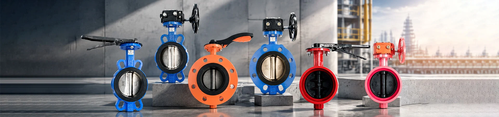
Wholesale electric actuators for dependable operation in demanding industrial environments
Choosing an electric actuator requires more than matching the valve size. Buyers also need to consider required torque, operating time, power supply, control signals, installation space, and environmental conditions. At Liangfa, we help customers evaluate these factors when selecting electric actuation solutions for industrial valves and automated pipeline systems. As a high-tech enterprise, we provide technical support to help match actuator configurations with project requirements and the intended operating environment.
Control Methods and Operation
The appropriate control method depends on whether a valve needs simple open-close operation or continuous adjustment. We recommend confirming the control strategy before choosing an actuator, especially when it will connect to a plant automation system.
On-Off Control
On-off actuators move a valve between its open and closed positions. They are commonly considered for pipeline isolation, water treatment equipment, and automated process switching. Buyers should check the required opening and closing time, operating frequency, and end-position feedback requirements.
Modulating Control
For applications that require flow adjustment, a modulating actuator can position the valve in response to a compatible control signal. Depending on the model, control systems may use signals such as 4–20 mA or 0–10 V. Confirm the actuator's input signal, feedback output, positioning accuracy, and controller compatibility before ordering.
Key Parameters for Selection
Incorrect actuator sizing can lead to incomplete valve movement, excessive mechanical load, or unnecessary cost. We recommend reviewing the valve manufacturer's torque requirements and the actual working conditions rather than selecting an actuator based only on nominal valve diameter.
| Selection Parameter | What Buyers Should Check |
|---|---|
| Output torque | Required valve torque, safety margin, and load variations during operation |
| Power supply | Available voltage, frequency, and electrical supply stability |
| Operating time | Required travel time and permitted operating frequency |
| Control signal | On-off commands, modulating input, and position feedback |
| Protection rating | Exposure to dust, water, humidity, and outdoor conditions |
| Mounting interface | Valve flange, drive dimensions, stem or shaft geometry, and mounting standard |
For reliable sizing, provide the valve type, model, torque requirement, operating pressure, medium, and expected duty cycle. If the valve manufacturer specifies different torque values for starting, running, and seating, these values should be considered during selection.
Check Valve Compatibility
An actuator must match the valve's mechanical interface and movement requirements. Before confirming an order, we recommend checking the mounting dimensions, drive connection, shaft shape, rotation angle, and available installation space.
Butterfly and Ball Valves
Quarter-turn electric actuators are commonly used with butterfly and ball valves. The actuator output must match the valve's required torque and rotation angle. Additional brackets or couplings may be necessary depending on the valve design.
Gate and Globe Valves
Some gate and globe valves require multi-turn or linear movement rather than quarter-turn rotation. Buyers should confirm the valve stem movement, thrust or torque requirements, and actuator type before selecting equipment.
Existing Valve Automation
When replacing a manual gearbox or an existing actuator, compare the mounting interface, electrical connections, travel limits, and control logic. Reusing an existing valve may be possible, but compatibility should be verified before installation.
Electrical and Environmental Requirements
Power and environmental conditions influence actuator reliability. We recommend confirming the local electrical supply and installation environment at the quotation stage so that the selected configuration meets the project's requirements.
- Power supply: Confirm the rated voltage and frequency available at the installation site.
- Ingress protection: Select a suitable enclosure rating for indoor, outdoor, dusty, or wet locations.
- Ambient temperature: Check the manufacturer's specified operating temperature range.
- Electrical safety: Verify grounding, cable entry, wiring protection, and applicable local requirements.
- Operating duty: Confirm the permitted operating frequency and duty rating for the intended process.
- Hazardous locations: Where explosive atmospheres may be present, use equipment specifically approved for the applicable hazardous-area classification.
Do not assume that every electric actuator is suitable for outdoor exposure, continuous modulation, or hazardous areas. The required protection and certification depend on the exact model and project conditions.
Installation and Commissioning
Before installation, isolate the power supply and make sure the valve is in a suitable position for mounting. Check the mechanical connection, fasteners, cable entries, and wiring diagram. The actuator should not be forced onto a misaligned valve stem or coupling.
During commissioning, verify the direction of rotation, open and closed travel limits, local controls, remote commands, and position feedback where fitted. For modulating systems, test the control signal across the required travel range and confirm that the actuator responds correctly to the controller.
We recommend recording the final settings and checking the complete valve assembly under the intended operating conditions before putting the equipment into service.
Common Operating Problems
When an actuator fails to operate as expected, the cause may be electrical, mechanical, or related to the control system. Check the manufacturer's troubleshooting instructions before disassembling the equipment.
| Symptom | Possible Cause | Recommended Check |
|---|---|---|
| No response | Power loss, incorrect wiring, or missing control command | Verify the supply, wiring diagram, and control signal |
| Stops before full travel | Incorrect travel limits, obstruction, or insufficient torque | Inspect the valve movement and verify actuator sizing |
| Incorrect rotation direction | Control configuration or wiring issue | Check the model-specific wiring instructions and settings |
| Position feedback is inaccurate | Incorrect calibration or feedback configuration | Check the position settings and controller input |
| Overheating or frequent trips | Excessive operating frequency, overload, or electrical problems | Review duty requirements and arrange qualified inspection |
Electrical inspection and repair should be carried out by qualified personnel. Always isolate the power supply before maintenance and follow the manufacturer's safety instructions.
Why Source from Liangfa?
At Liangfa, we work with customers to clarify valve compatibility, torque requirements, control methods, power supply, and environmental conditions before confirming an actuator configuration. As a high-tech enterprise, we focus on technical communication and application-based product selection to help reduce mismatches between the actuator and the equipment it operates.
To help us evaluate your project, send us the valve model or technical drawing, required torque, power supply, control method, installation environment, and target quantity. We can review these details and confirm the applicable product options and specifications.
Frequently Asked Questions
Can an electric actuator operate a valve remotely?
Yes, if the selected actuator supports the required remote control interface. Depending on the model, this may involve discrete open-close commands or a compatible modulating signal. Confirm the input and feedback interfaces before connecting it to a PLC or building management system.
How do I determine the required actuator torque?
Start with the valve manufacturer's torque data for the actual pressure and operating conditions. Consider starting torque, running torque, seating requirements, and an appropriate design margin. Do not rely on valve diameter alone.
Can I replace a pneumatic actuator with an electric one?
In some installations, yes. The valve interface, required torque, movement angle, available space, power supply, control strategy, and operating conditions must all be checked. The complete assembly should be assessed before replacement.
Does an electric actuator include position feedback?
That depends on the model and configuration. Some units support position indication or feedback signals, while others provide basic open-close operation. Specify whether your control system needs end-position switches, analog feedback, or other signals.
What information should I send for a quotation?
Please provide the valve type and model, required torque, supply voltage, control method, operating time, environmental conditions, and quantity. Drawings and existing actuator details are also helpful when replacing equipment.
- View as
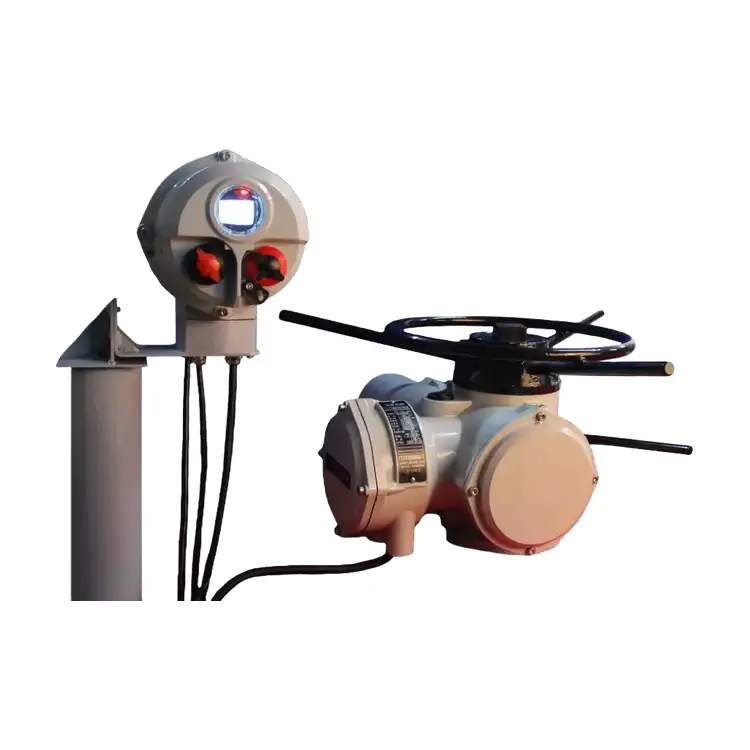
Split-type Multi-turn Electric Actuator
Liangfa provides split-type multi-turn electric actuators for automated control of gate valves, globe valves, and other compatible industrial valves. Featuring a separate mechanical drive unit and remote control box, our actuators support on-off and modulating control, with optional 4–20 mA signals and fieldbus communication.
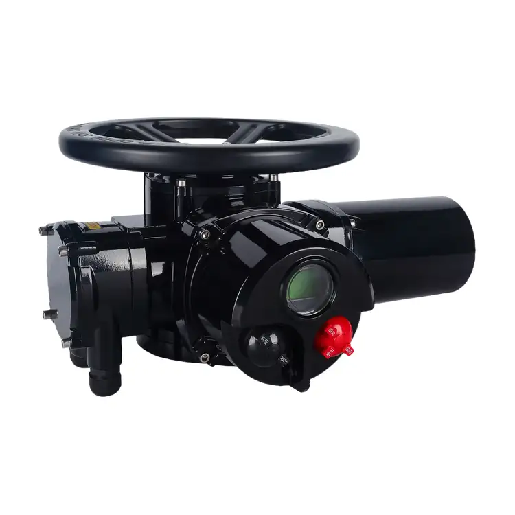
Explosion-Proof Multi-turn Electric Actuator
The Explosion-Proof Multi-Turn Electric Actuator is designed for reliable valve automation in hazardous industrial environments, including oil and gas pipelines, petrochemical plants, and chemical processing facilities. With explosion-proof options of Ex d IIB T4 and Ex d IIC T4, torque outputs from 30 to 5000 N·m, and compatibility with gate, globe, knife-gate, and other multi-turn valves, it supports on-off and modulating control to meet different operating requirements.
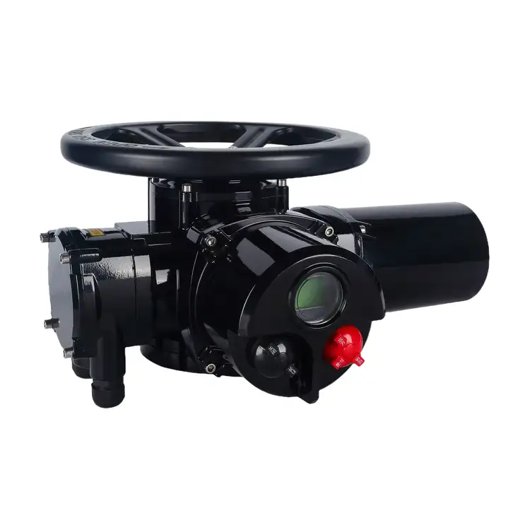
Intelligent Multi-turn Electric Actuator
Liangfa supplies intelligent electric actuators for automated valve control in water treatment, power generation, heating, petrochemical processing, and other industrial applications. Designed for multi-turn valves, the Intelligent Multi-turn Electric Actuator combines absolute position detection, digital parameter setting, torque protection, and flexible control options to support reliable valve operation.
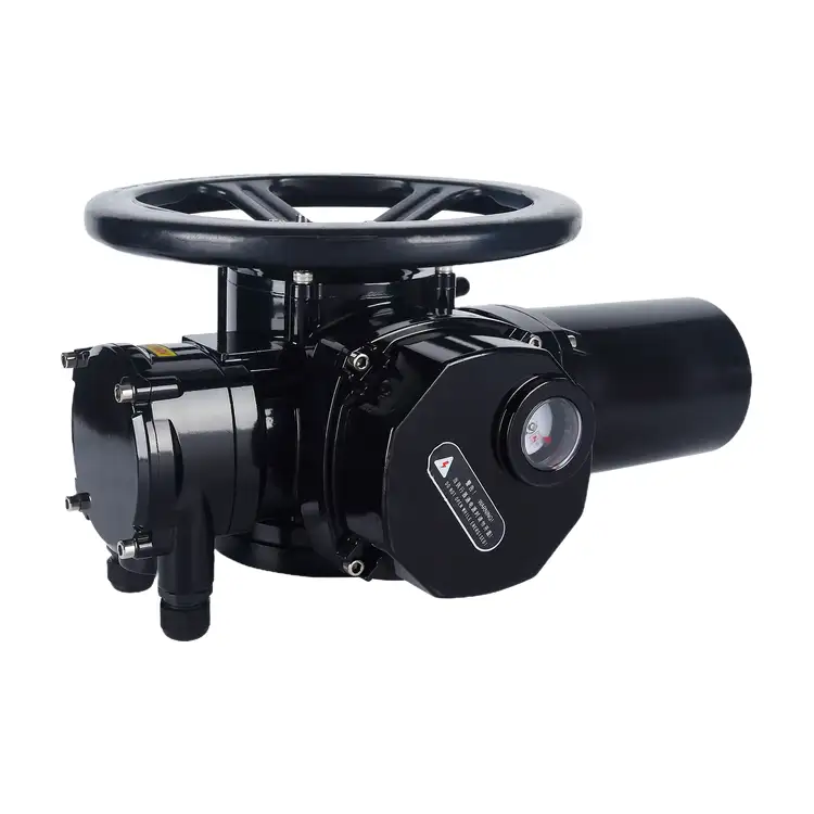
On-off Multi-turn Electric Actuator
Liangfa's On-off Multi-turn Electric Actuator is designed for reliable opening and closing of gate valves, globe valves, and other compatible multi-turn valves in water treatment, sewage, power generation, heating, and industrial pipeline systems. With output torque ranging from 10 to 2500 N·m, ISO5210 mounting options, and AC380V three-phase power as standard, it supports flexible configuration for different valve and site requirements.
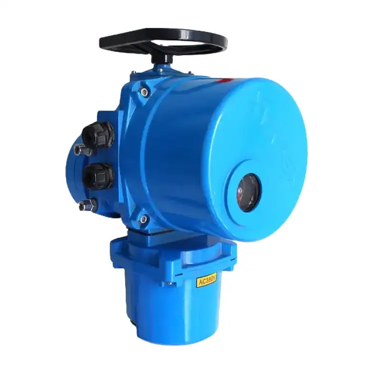
QT Series Explosion-Proof Electric Actuator
Liangfa's QT Series Explosion-Proof Electric Actuator is designed for 90° operation of compatible butterfly valves, ball valves, and plug valves in hazardous industrial environments. With output torque from 40 N·m to 2500 N·m, ISO 5211 mounting options, and AC220V, AC380V, or customized DC24V power supplies, it supports flexible valve automation for petrochemical, gas, chemical, and water treatment applications.
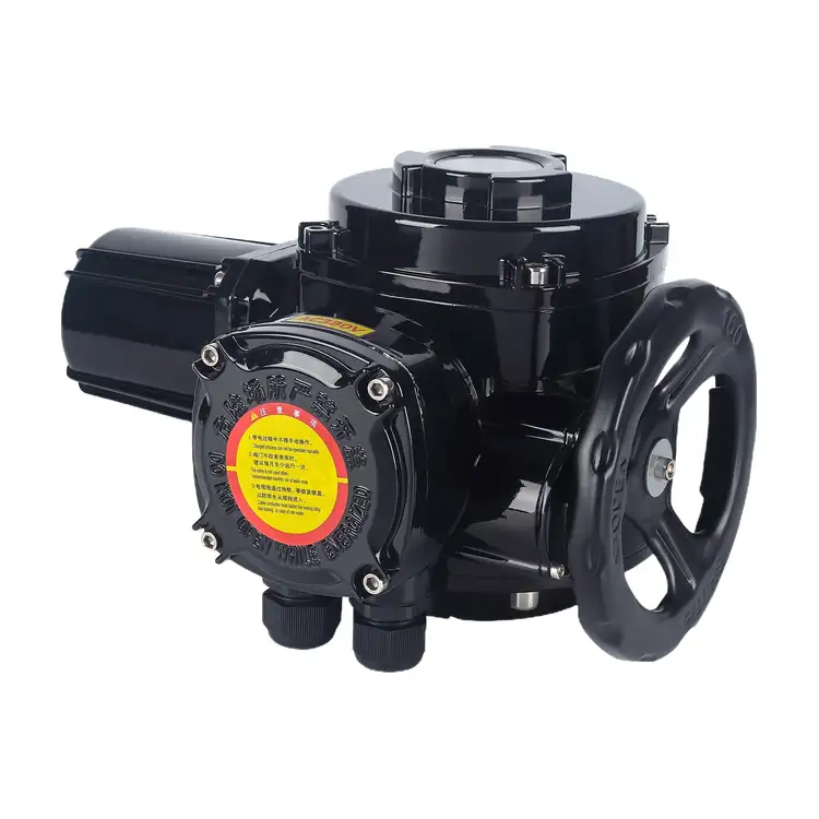
QB Series Explosion-Proof Electric Actuator
Liangfa's QB Series Explosion-Proof Electric Actuator is designed for 90° valve automation in hazardous industrial environments, including petrochemical plants, gas facilities, and approved underground mining applications. With torque options ranging from 20 N·m to 12,000 N·m across the listed model series, ISO 5211 mounting options, and AC220V, AC380V, or specified mining AC127V power supplies, it supports a range of compatible butterfly valves, ball valves, plug valves, and dampers.
Liangfa is a professional Electric Actuator manufacturer and supplier in China. We have an experienced sales team, professional technicians, and an after-sales service team.
News Recommendations