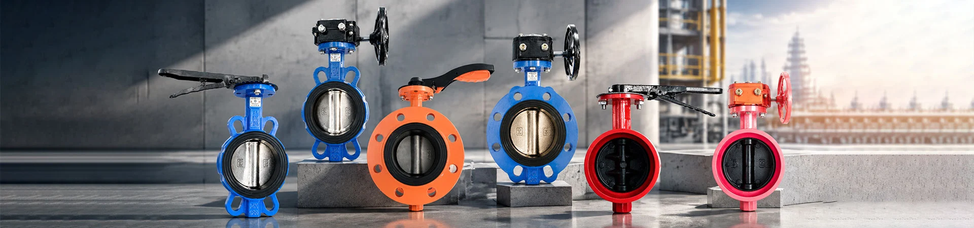
Wholesale Part-turn Electric Actuators for Valve Automation
At Liangfa, we provide part-turn electric actuators for valves and other equipment that require controlled rotary movement over a limited angle. These actuators convert electrical power into mechanical torque to operate compatible quarter-turn or other specified part-turn devices.
They are commonly considered for butterfly valves, ball valves, dampers, and similar equipment, provided the actuator's travel range, torque output, and mounting interface match the driven device. As a high-tech enterprise, we help customers evaluate operating requirements and select a suitable actuator configuration for their projects.
Confirm the Required Rotation
A part-turn actuator is designed to rotate through a limited angle rather than continuously rotating like a multi-turn actuator. Many valve applications use a 90-degree movement between open and closed positions, but the required travel depends on the driven equipment.
When selecting a part-turn electric actuator, we recommend confirming the valve's required travel angle, opening and closing direction, and end-position requirements. If the driven equipment requires more than a standard quarter turn, verify that the selected model supports the required travel range before ordering.
Match Torque to the Load
Torque is one of the most important selection parameters. An actuator must provide enough output torque to move the valve or equipment under its actual operating conditions. The required torque can vary with valve size, differential pressure, seal friction, temperature, and service history.
| Selection Parameter | Why It Matters |
|---|---|
| Required operating torque | Determines whether the actuator can move the driven equipment reliably. |
| Supply voltage | Must match the actuator's rated electrical supply. |
| Travel angle | Defines the movement range needed by the valve or mechanism. |
| Operating time | Helps establish whether the actuator's travel speed suits the process. |
| Duty cycle | Indicates how frequently and for how long the actuator is expected to operate. |
We recommend using the valve manufacturer's torque data and allowing for the specified service conditions rather than selecting an actuator based on valve diameter alone. Excessive oversizing can also affect control suitability, so the actuator and driven equipment should be assessed as a matched assembly.
Check the Mounting Interface
Even when the torque and rotation range are suitable, the actuator must connect correctly to the valve or equipment. The mounting interface, drive shape, shaft dimensions, and bolt pattern should be verified before installation.
- Mounting standard: Confirm the applicable flange or mounting interface dimensions.
- Drive connection: Check the output drive shape and dimensions against the driven shaft.
- Installation position: Ensure there is enough clearance for wiring, access, and maintenance.
- Mechanical alignment: Prevent misalignment that may increase resistance or damage connected components.
When replacing an existing actuator, we recommend comparing the mounting drawings and output-drive details instead of relying on the model name or nominal torque rating alone.
Choose the Control Arrangement
The required control function determines which electrical features the actuator needs. Some applications only require movement between open and closed positions, while others need intermediate positioning or feedback to a control system.
| Control Requirement | Points to Confirm |
|---|---|
| On-off operation | Opening and closing commands, travel limits, and status indication. |
| Positioning control | Whether the model supports intermediate positioning and the required control signal. |
| Remote monitoring | Available feedback contacts, position signals, and electrical interfaces. |
| Local operation | Whether local controls or a manual override are required and supported. |
Not every part-turn electric actuator supports modulating control, remote communication, or manual override. At Liangfa, we recommend confirming the actual functions available on the selected model before finalizing the control-system design.
Set the Travel Limits Correctly
Travel limits define the permitted end positions of the actuator. Correct adjustment helps prevent the actuator from driving the connected valve beyond its intended travel and supports consistent positioning. The adjustment method depends on the actuator design and may involve mechanical stops, limit switches, or electronic settings.
During commissioning, verify the open and closed positions against the valve manufacturer's requirements. Check the direction of movement, control wiring, feedback signals, and any torque or overload protection settings. Follow the product instructions and avoid forcing the actuator against an incorrectly adjusted stop.
If the actuator stops before reaching the expected position, inspect the limit settings, supply voltage, mechanical alignment, and resistance from the driven equipment. Electrical and mechanical checks should be carried out by qualified personnel using the appropriate isolation procedures.
Consider the Installation Environment
The operating environment affects enclosure selection, electrical protection, and maintenance frequency. An actuator installed indoors may face different conditions from equipment exposed to rain, dust, humidity, vibration, or temperature extremes.
- Confirm the required enclosure protection level for the installation location.
- Check the permitted ambient temperature and humidity range.
- Review cable entry, wiring protection, and grounding requirements.
- Consider vibration, corrosion, and access for inspection.
- For hazardous areas, verify that the specific actuator has the required certification and is suitable for the intended zone.
We recommend checking the product documentation for the selected model's actual environmental ratings. Protection levels and hazardous-area approvals should never be assumed without the relevant technical evidence.
Plan Routine Inspection
Regular inspection helps identify developing problems before they interrupt the process. Check the actuator housing, mounting bolts, electrical connections, cable entries, and output coupling for visible damage or loosening. Where applicable, verify position indication and test the operating cycle according to the maintenance plan.
If the actuator becomes noisy, moves unevenly, overheats, or fails to complete its travel, stop and investigate the cause before returning it to service. Possible causes include incorrect supply voltage, excessive load, mechanical binding, unsuitable duty cycle, or incorrect limit settings. Follow the manufacturer's maintenance instructions and do not open electrical enclosures while energized unless the procedure explicitly permits it.
Provide These Details for Selection
To help us recommend a suitable actuator, please provide Liangfa with the following information:
- Driven valve or equipment type
- Required rotation angle and travel direction
- Required operating torque and available sizing data
- Supply voltage and frequency
- Required operating time and duty cycle
- On-off or positioning control requirements
- Mounting interface and output-drive dimensions
- Required feedback, local controls, and communication features
- Ambient conditions and any project-specific certifications
As a high-tech enterprise, Liangfa provides product information and technical support to help customers assess actuator compatibility. Complete application details make it easier to compare models, confirm interfaces, and reduce problems during installation and commissioning.
Frequently Asked Questions
What is the difference between a part-turn and a multi-turn actuator?
A part-turn actuator rotates through a limited angle, commonly around 90 degrees for many valve applications. A multi-turn actuator is designed to deliver multiple rotations and is often used with equipment such as rising-stem or gate valves that require repeated turns. The correct type depends on the driven equipment's movement requirements.
Can one actuator operate different valve types?
Potentially, if each valve's torque requirement, travel angle, mounting interface, and control needs are compatible with the actuator. Compatibility should be checked for each application rather than assumed from the actuator's nominal torque rating.
Does a higher torque rating always mean better performance?
No. The actuator must provide sufficient torque for the required load, but excessive oversizing may be inefficient or unsuitable for some positioning applications. Use the driven equipment's torque data and operating conditions to select an appropriate model.
Why does the actuator stop before the valve reaches its end position?
Possible causes include incorrect travel-limit settings, low supply voltage, excessive mechanical resistance, misalignment, or a torque protection setting that is too restrictive for the application. Check the manufacturer's troubleshooting procedure and isolate the equipment safely before inspection.
Can I replace an actuator without replacing the valve?
In some cases, yes. The replacement must match the valve's required torque, travel range, mounting interface, output drive, electrical supply, and control requirements. Confirm the dimensions and specifications before ordering to avoid additional adapters or installation work.
- View as
QT Series Explosion-Proof Electric Actuator
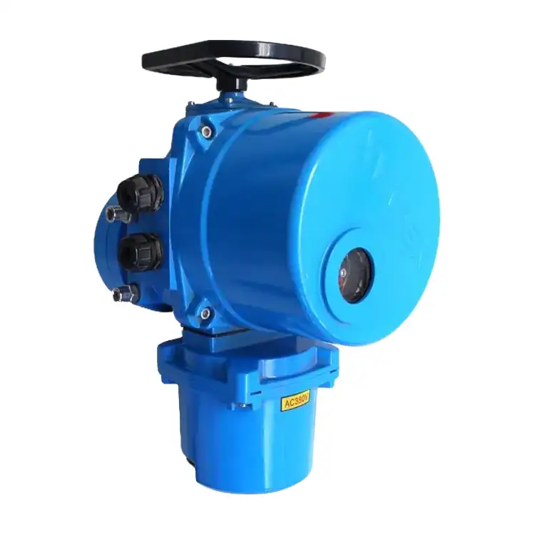
Liangfa's QT Series Explosion-Proof Electric Actuator is designed for 90° operation of compatible butterfly valves, ball valves, and plug valves in hazardous industrial environments. With output torque from 40 N·m to 2500 N·m, ISO 5211 mounting options, and AC220V, AC380V, or customized DC24V power supplies, it supports flexible valve automation for petrochemical, gas, chemical, and water treatment applications.
QB Series Explosion-Proof Electric Actuator
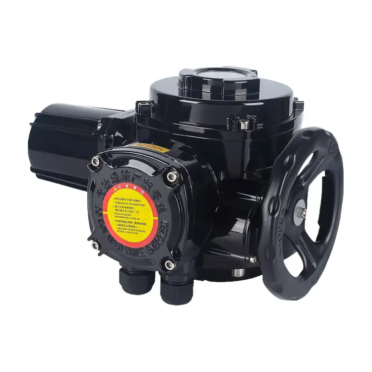
Liangfa's QB Series Explosion-Proof Electric Actuator is designed for 90° valve automation in hazardous industrial environments, including petrochemical plants, gas facilities, and approved underground mining applications. With torque options ranging from 20 N·m to 12,000 N·m across the listed model series, ISO 5211 mounting options, and AC220V, AC380V, or specified mining AC127V power supplies, it supports a range of compatible butterfly valves, ball valves, plug valves, and dampers.
Compact Explosion-Proof Electric Actuator
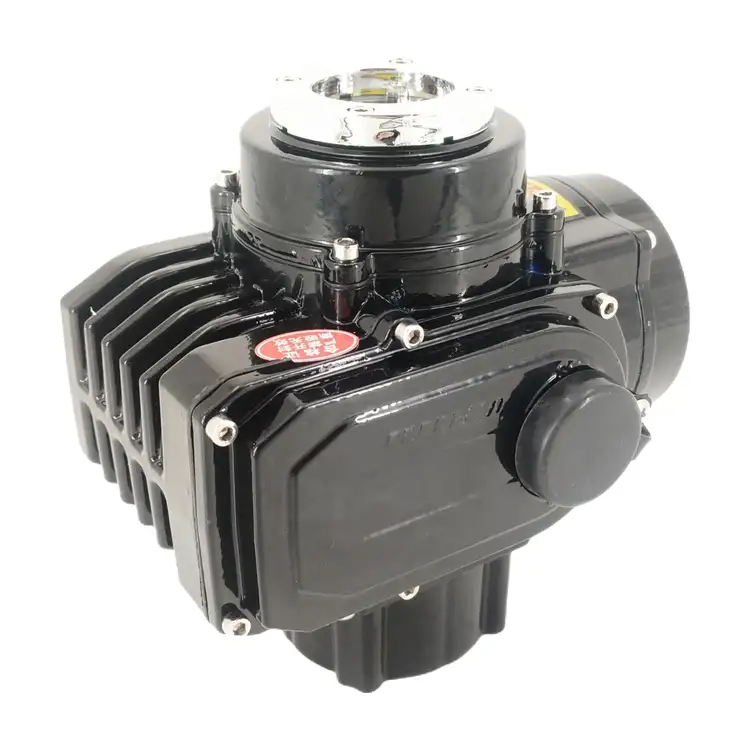
Liangfa's Compact Explosion-Proof Electric Actuator is designed for 90° valve automation in hazardous industrial environments where installation space is limited. With torque options from 50 to 600 N·m, ISO 5211 mounting interfaces, and AC220V, AC380V, or DC24V power supply configurations, it can be matched with compatible butterfly valves, ball valves, and plug valves.
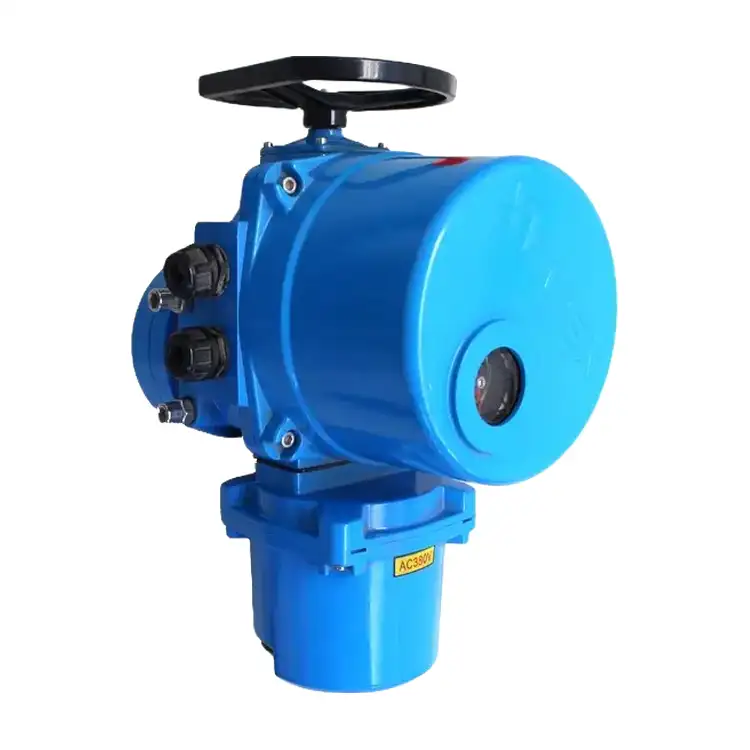
QT Series Intelligent Electric Actuator
Liangfa's QT Series Intelligent Electric Actuator is designed for precise 90° rotary valve control in water treatment, HVAC, fire protection and industrial pipeline systems. With torque options from 10 to 2000 N·m, standard IP67 protection and ISO 5211 mounting interfaces, it supports both on-off and 4–20 mA modulating control. Optional Modbus-RTU communication enables integration with compatible PLC and DCS systems, while multiple power supply options and an explosion-proof version support different installation requirements.
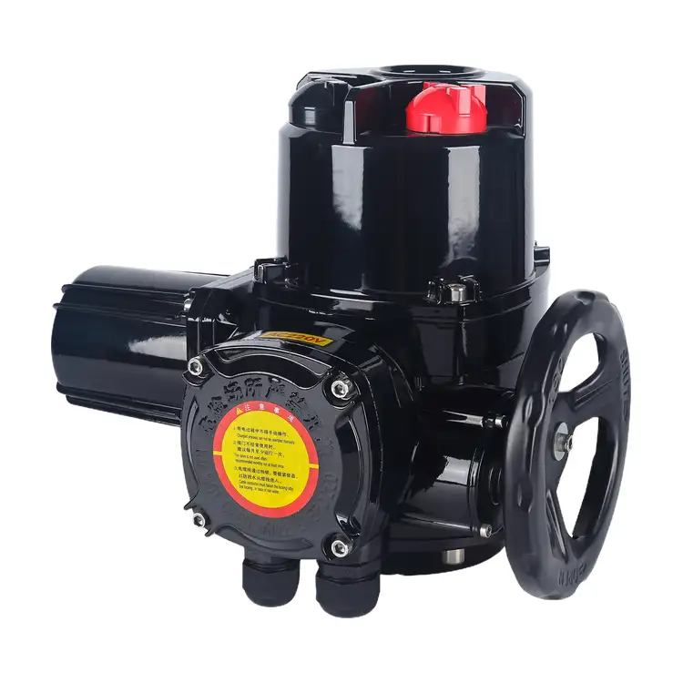
QB Series Intelligent Electric Actuator
Liangfa's QB Series Intelligent Electric Actuator is designed for 90° rotary valve automation in industrial plants, mining facilities and other demanding environments. With torque options ranging from 20 to 12,000 N·m, it supports compatible butterfly valves, ball valves, plug valves and dampers. Available configurations include on-off and 4–20 mA modulating control, multiple power supply options, and explosion-proof versions for specified hazardous areas.
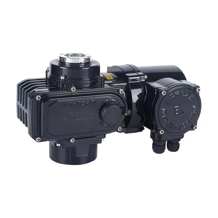
Compact Intelligent Electric Actuator
Liangfa's Compact Intelligent Electric Actuator is designed for precise 90° rotary valve control in space-limited industrial installations. It supports 4–20 mA signal input and position feedback, with optional Modbus RTU communication for integration with compatible PLC and DCS systems. Featuring ISO 5211 mounting options, AC220V, AC380V and DC24V power supplies, and standard IP65 protection with optional IP67, it is suitable for compatible butterfly valves, ball valves, plug valves and air dampers.
Liangfa is a professional Part-turn Electric Actuator manufacturer and supplier in China. We have an experienced sales team, professional technicians, and an after-sales service team.
News Recommendations