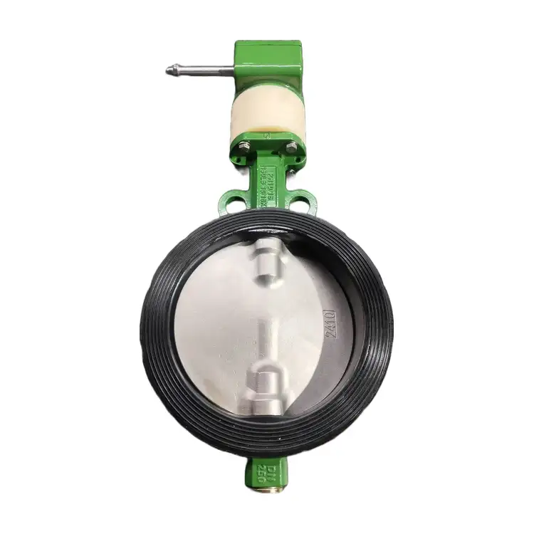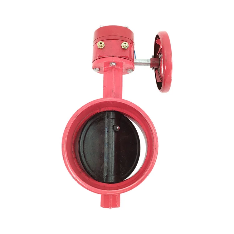
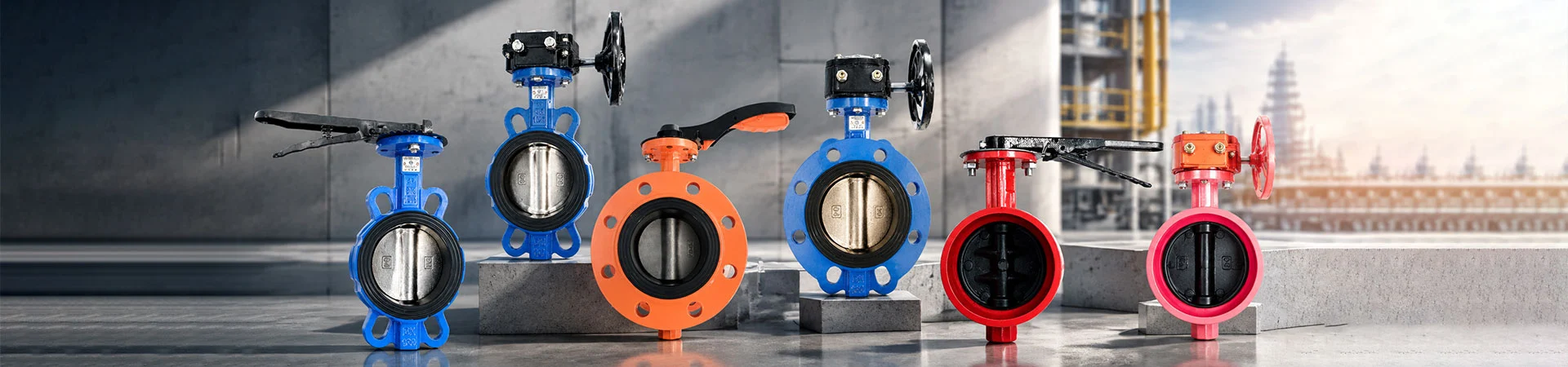
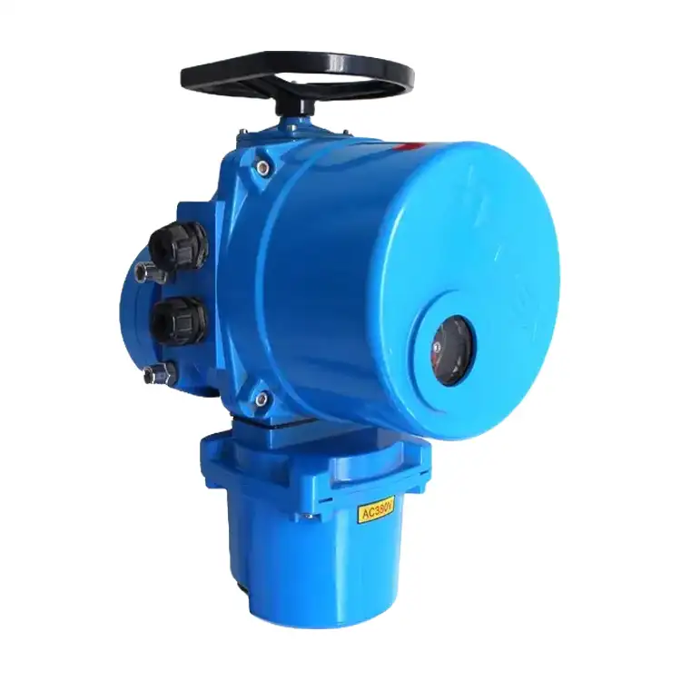
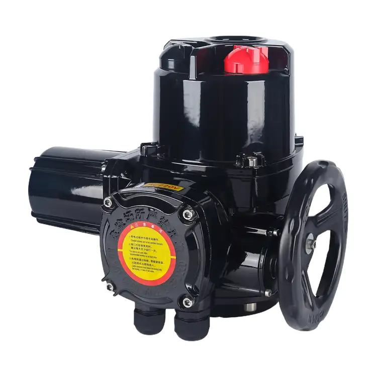
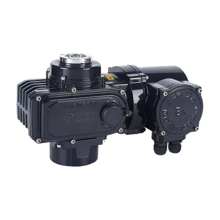
QT Series Explosion-Proof Electric Actuator
Liangfa's QT Series Explosion-Proof Electric Actuator is designed for 90° operation of compatible butterfly valves, ball valves, and plug valves in hazardous industrial environments. With output torque from 40 N·m to 2500 N·m, ISO 5211 mounting options, and AC220V, AC380V, or customized DC24V power supplies, it supports flexible valve automation for petrochemical, gas, chemical, and water treatment applications.
The QT Series Explosion-Proof Electric Actuator is available in on-off and intelligent modulating versions. The on-off version supports full-open and full-close operation, while the modulating version can support 4–20 mA control and position feedback when specified. Standard configurations use Ex db IIB T6 Gb protection and an IP67 enclosure; Ex db IIC T6 Gb and IP68 options are available for applicable models and must be confirmed against the required certification.
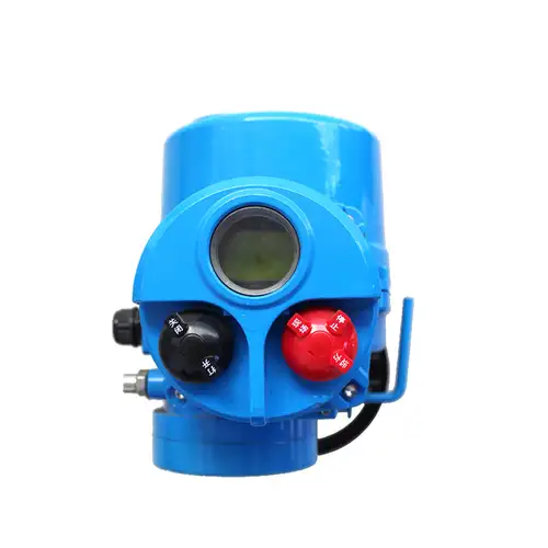
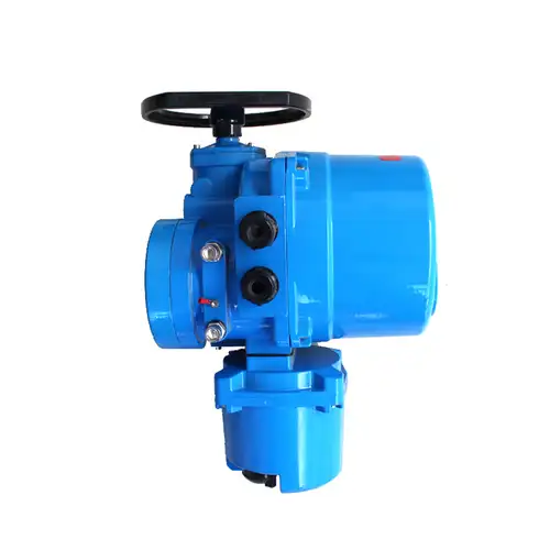
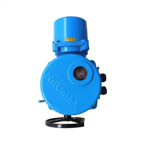
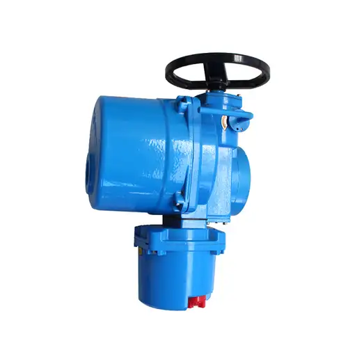
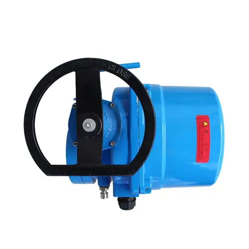
Choose the Right Drive for Your Valve
Selecting a QT Series Explosion-Proof Electric Actuator involves more than matching the valve diameter. We recommend checking the valve's required operating torque, 90° travel, mounting dimensions, power supply, and control method before choosing a model. Valve torque can change with differential pressure, seat material, fluid characteristics, deposits, temperature, and service frequency.
Torque and Operating Time
The available output torque ranges from 40 N·m to 2500 N·m. The following table lists reference ratings for standard QT frames. Confirm the final torque and operating time against the specific model's technical documentation.
| Model | Rated Output Torque | Reference 90° Operating Time |
|---|---|---|
| QT-04 | 40 N·m | 10 s |
| QT-06 | 60 N·m | 10 s |
| QT-08 | 80 N·m | 10 s |
| QT-10 | 100 N·m | 12 s |
| QT-15 | 150 N·m | 12 s |
| QT-20 | 200 N·m | 15 s |
| QT-30 | 300 N·m | 15 s |
| QT-40 | 400 N·m | 18 s |
| QT-60 | 600 N·m | 18 s |
| QT-80 | 800 N·m | 20 s |
| QT-100 | 1000 N·m | 20 s |
| QT-150 | 1500 N·m | 25 s |
| QT-200 | 2000 N·m | 25 s |
| QT-250 | 2500 N·m | 30 s |
These figures are reference values, not a substitute for valve torque data. We generally recommend evaluating a preliminary torque margin of 1.2–1.5 against the actual valve operating torque, with the final factor determined by the valve manufacturer, process conditions, and operating requirements. Do not exceed the actuator's rated output torque.
Check the Valve Interface
The standard mounting interface follows ISO 5211, with F03, F04, F05, F07, F10, F12, and F14 options. Before ordering, verify the valve flange, stem diameter, stem height, and output-shaft shape. Square-drive connections are common; keyed round shafts or other connections should be confirmed for the selected configuration. Correct alignment helps reduce additional mechanical load and unnecessary over-torque trips.
Select the Control Method
| Control Version | Main Function | Typical Control Arrangement |
|---|---|---|
| On-off | Moves the valve between fully open and fully closed positions | Open/close commands with configured limit or status contacts |
| Intelligent modulating | Adjusts valve position in response to a control signal | 4–20 mA input and position feedback, local display, and compatible DCS or PLC integration |
If your process requires only isolation or emergency shut-off, an on-off model may be appropriate. For continuous flow adjustment, specify the intelligent modulating version and confirm its input/output signals, positioning accuracy, duty rating, and compatibility with the control system. The QT Series Explosion-Proof Electric Actuator's explosion-proof construction does not by itself establish that a complete safety instrumented function is SIL-certified.
Explosion Protection for the Installation Site
Hazardous-area suitability depends on the complete installation, including the gas group, temperature class, equipment protection level, zone classification, cable entries, and local regulations. Our standard specification is Ex db IIB T6 Gb, with an Ex db IIC T6 Gb upgrade available for applicable models. Buyers should confirm that the selected model's nameplate and valid certification cover the intended location and actual hazardous substances.
| Specification | Standard or Optional Configuration | Selection Notes |
|---|---|---|
| Explosion protection | Ex db IIB T6 Gb standard; Ex db IIC T6 Gb upgrade | Confirm the exact gas group, temperature class, equipment protection level, and certification |
| Enclosure protection | IP67 standard; IP68 optional | IP68 requires a suitable certified configuration and defined immersion conditions |
| Power supply | AC220V, AC380V, customized DC24V | Confirm the supply, wiring arrangement, and certificate compatibility |
| Ambient temperature | -25°C to +80°C for the stated standard range | Check the nameplate and temperature limits of the specific version and accessories |
| Corrosion protection | Enhanced coating and selected corrosion-resistant hardware options | Specify salt spray, chemical exposure, humidity, and outdoor conditions |
The standard IIB version should not be assumed suitable for hydrogen, acetylene, or other gases that require IIC equipment. A higher gas-group marking must be confirmed for the exact model and application. This series is intended for applicable Class II industrial explosive-gas environments, not Class I underground coal mines.
Protection Against Moisture and Heat
IP67 protection is suitable for many outdoor installations exposed to rain and temporary immersion under the specified test conditions, but it does not mean that the actuator can remain submerged indefinitely. Where prolonged immersion is expected, discuss the optional IP68 configuration and its approved immersion limits with us.
In humid locations or sites with large day-to-night temperature changes, an optional dehumidifying heater can help reduce internal condensation. Low-temperature configurations may require a heater and suitable lubricant, while hot installations may need a heat shield, thermal isolation, or a revised selection. The full assembly must remain within its certified ambient-temperature limits.
Mechanical Design and Operating Safeguards
Gear Drive and Position Holding
The dual worm-gear arrangement is designed to deliver controlled quarter-turn movement and help resist unintended valve-position changes when power is removed. Actual position-holding performance depends on the selected configuration, valve load, and installation conditions, so the valve and actuator must be checked together.
Limit and Over-Torque Protection
Travel-limit protection helps stop movement at the configured end positions, while over-torque protection helps identify excessive mechanical resistance. A Class F insulated, enclosed motor with overheat protection is specified for the series. These functions support equipment protection but do not replace correct sizing, commissioning, process interlocks, or required independent safety devices.
Manual Operation During a Power Loss
A semi-automatic manual-electric clutch and handwheel are provided for manual operation on the configured model. Follow the product instructions when switching modes, and isolate electrical power before carrying out maintenance. After power returns, confirm that the actuator has returned to the intended operating mode and that the valve position is correct.
Reference Valve Matching
The table below is an illustrative reference for soft-seated butterfly valves handling clean water at PN10, using an assumed preliminary safety factor of 1.2. Actual torque depends on valve design, seat material, pressure differential, and service conditions. Obtain the valve manufacturer's torque data before finalizing the actuator.
| Example Valve | Estimated Torque | Reference QT Model |
|---|---|---|
| DN50 D971X | 30 N·m | QT04 |
| DN80 D971X | 50 N·m | QT06 |
| DN100 D971X | 70 N·m | QT08 |
| DN150 D971X | 120 N·m | QT15 |
| DN200 D971X | 180 N·m | QT20 |
| DN250 D971X | 280 N·m | QT30 |
| DN300 D971X | 380 N·m | QT40 |
| DN350 D971X | 550 N·m | QT60 |
| DN400 D971X | 720 N·m | QT80 |
These examples are not universal sizing recommendations. Sewage, suspended particles, aged pipelines, high differential pressure, or infrequent operation can increase valve torque. Please send us the valve model, operating conditions, and required control method for a more reliable selection.
Installation and Commissioning Checks
Before Mounting
Check the nameplate, model, rated torque, supply voltage, explosion marking, certification documents, housing, cable entries, gaskets, and flameproof joints. Manually check that the valve travels smoothly and that the stem and flange match the actuator. Do not install a damaged unit or one with incomplete explosion-protection sealing components.
Mounting and Wiring
Align the actuator and valve shafts, seat the mounting flanges evenly, and tighten the fasteners in a balanced sequence. Connect protective earthing and use cable glands and blanking plugs suitable for the certified hazardous-area installation. Disconnect power before opening the terminal cover. Never energize the QT Series Explosion-Proof Electric Actuator with a missing, damaged, or improperly secured cover or seal.
Do not drill, weld, strike, or machine the flameproof enclosure or joint surfaces. Such changes may compromise explosion protection and invalidate the applicable certification. The actuator must not carry pipeline loads; provide appropriate pipe supports.
Setting Limits and Testing
Follow the model-specific manual to set the open and closed travel limits and verify over-torque protection. Do not raise the torque setting arbitrarily to overcome a jammed valve. Test local and remote commands, limit contacts, position feedback, fault alarms, and heater operation where fitted. For three-phase models, confirm the supply and phase-sequence protection according to the manufacturer's instructions.
Complete no-load and loaded functional tests under controlled conditions before returning the valve to service. For hazardous-area commissioning, use qualified personnel and follow the site's isolation, permit-to-work, and explosion-safety procedures.
Maintenance and Fault Diagnosis
Regular inspection helps identify loose terminals, damaged cable glands, corrosion, condensation, abnormal vibration, and changes in operating performance. Inspection intervals should reflect the site environment, operating frequency, and the manufacturer's maintenance instructions.
| Symptom | Possible Cause | Recommended Check |
|---|---|---|
| No response after power-up | Supply failure, loose wiring, motor thermal protection, or oxidized terminals | Isolate power and have qualified personnel check the supply and connections |
| Motor runs but valve does not move | Clutch not engaged, seized valve stem, or damaged drive component | Isolate the unit and inspect the valve and drive coupling |
| Repeated over-torque trips | Valve obstruction, excessive operating torque, misalignment, or incorrect settings | Check the valve condition and alignment before resetting protection |
| Incorrect position feedback | Travel calibration error or feedback-device fault | Check calibration and the feedback device using the relevant manual |
| Internal condensation | High humidity, temperature fluctuations, or a heater fault | Isolate the unit and inspect sealing and heater operation |
| Handwheel feels stiff | Valve blockage, degraded lubricant, or mechanical wear | Check the valve and gear mechanism according to the maintenance procedure |
Before maintenance in a hazardous area, isolate the electrical supply, apply the site's lockout/tagout procedure, and confirm that the area is safe. Never open the enclosure while energized or while an explosive atmosphere may be present. Protect flameproof surfaces, use approved replacement parts, and follow the manufacturer's instructions for reassembly and inspection.
Manufacturing and Quality Support
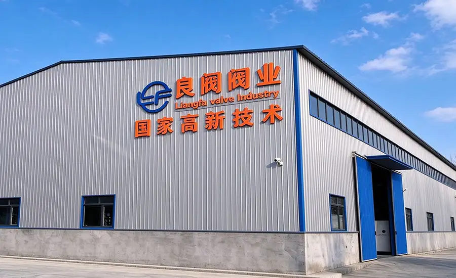
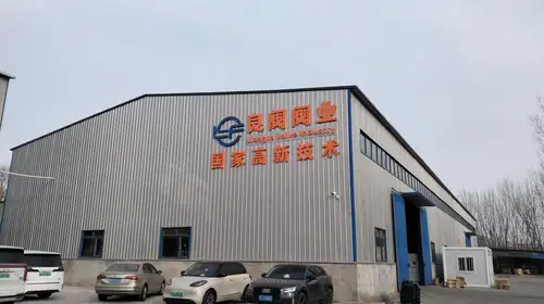
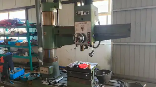
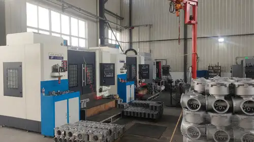
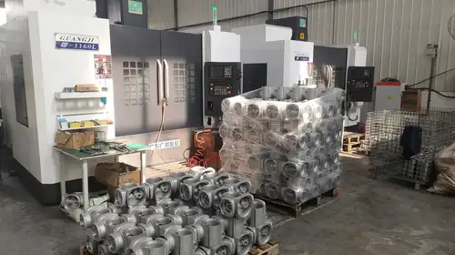
At Liangfa, we support customers from technical selection through production, inspection, delivery, and after-sales service. As a high-tech enterprise, we provide product drawings, configuration guidance, and technical communication to help customers check the actuator against their valve and site requirements.
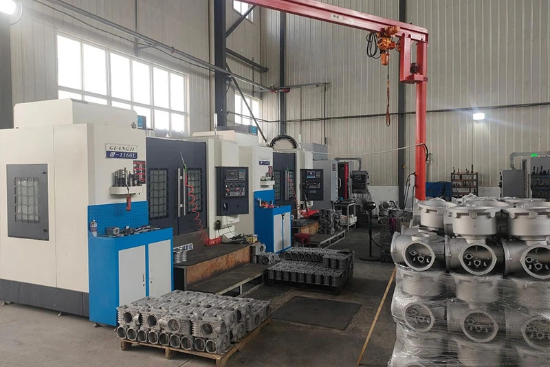
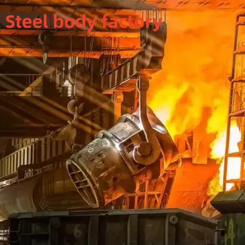
Our production workflow covers casting, precision machining, coating, assembly, and export packaging. Inspection requirements and available documentation are confirmed for the order; customers can request the applicable test records and explosion-protection certificates for the selected model.
Factory Tour
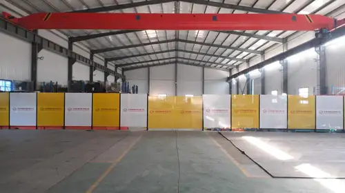
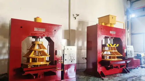
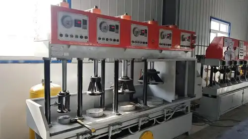
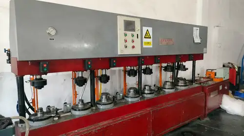
Export Packing and Delivery
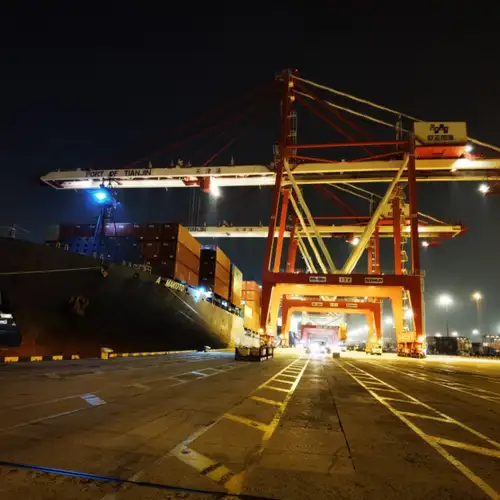
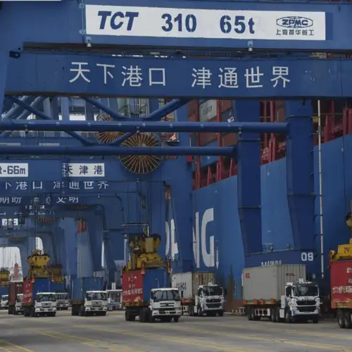
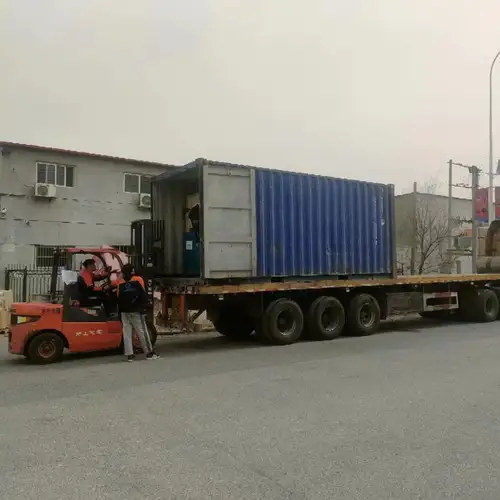
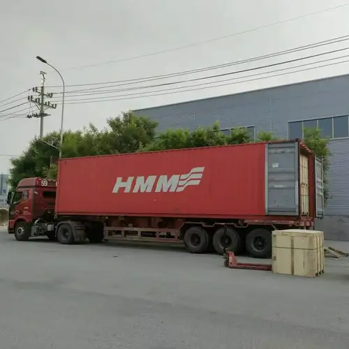
We provide export packing and coordinate sea freight or land transport according to order requirements and destination. Before shipment, we confirm the product configuration, packing details, and required shipping documents with the customer.
Industrial Applications
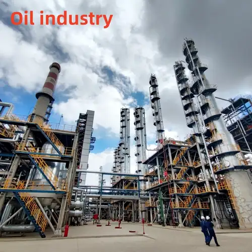
Oil Storage and Petrochemical Plants
Used with compatible quarter-turn valves for pipeline isolation and process control in oil depots, pump houses, loading areas, and petrochemical facilities. The selected explosion rating must match the site's hazardous-area classification and the substances present.
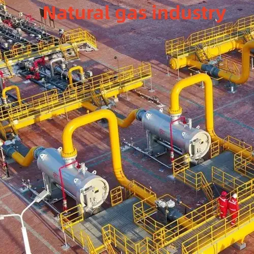
Natural Gas and LPG Systems
Suitable for compatible valve automation at gas stations, pressure-regulating facilities, and gas transmission systems when the actuator's certified gas group and control arrangement meet project requirements. Emergency-shut-off use requires a complete system-level safety assessment.
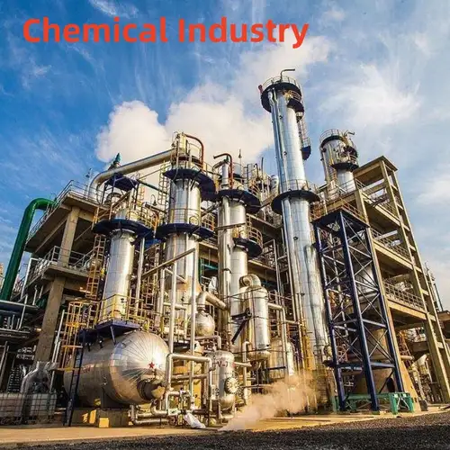
Chemical and Pharmaceutical Production
Supports valve operation in chemical and pharmaceutical processes involving compatible flammable solvents and volatile media. For corrosive chemicals, verify material compatibility, coating suitability, and the required hazardous-area certification.
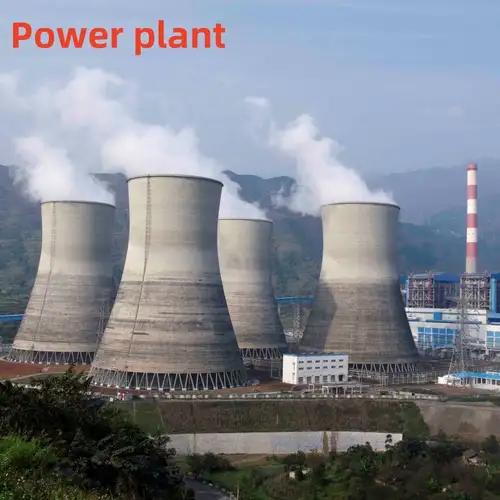
Water Treatment and Sewage Facilities
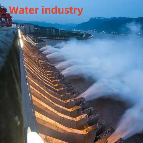
Can operate compatible butterfly valves in pump rooms, reclaimed-water systems, and sewage pretreatment areas. Where sediment or fibrous material raises valve resistance, use actual operating torque data rather than sizing by nominal diameter alone.
Heating and HVAC Systems
Automates compatible quarter-turn valves in circulation-water and heat-exchange systems. Confirm the ambient temperature and any heat transferred from adjacent pipes before selecting the actuator configuration.
Coastal and Offshore Facilities
For installations exposed to salt spray and high humidity, enhanced corrosion protection and suitable hardware can be specified. Confirm the coating and fastener options according to the site's actual corrosive exposure.
Grain and Feed Processing
Valve automation may be used in facilities where combustible dust or flammable gas hazards are present, but gas explosion protection alone does not establish suitability for a combustible-dust hazard. Confirm the required dust protection and equipment certification for the installation.
Technical and After-Sales Support
Before Ordering
We provide model-selection assistance based on valve type, operating torque, nominal size, pressure, medium, ambient temperature, power supply, and control requirements. Product drawings, technical parameters, configuration details, and quotations can be provided for project evaluation. Custom options and sample availability are subject to technical review.
During Production and Delivery
We confirm the order configuration and applicable inspection requirements before shipment. Inspection records, relevant certificates, and export documents can be arranged according to the order. Production progress and loading information are shared with customers as agreed.
After-Sales Assistance
We offer remote guidance for installation, commissioning, operation, and maintenance, as well as technical consultation for valve replacement or pipeline modifications. Spare-parts availability depends on the specific actuator and valve configuration. Our stated warranty period is 12 months from shipment, subject to the agreed sales contract and warranty terms.
Frequently Asked Questions
Can this actuator be used with a butterfly valve or a ball valve?
Yes. It is designed for compatible 90° quarter-turn valves, including butterfly, ball, and plug valves. Confirm the valve's torque requirement, ISO 5211 mounting interface, stem dimensions, and travel before ordering.
When should I choose IIC instead of IIB?
The required gas group depends on the hazardous substances and the site's classification. Some gases, including hydrogen and acetylene, may require IIC-rated equipment. Do not select a version from the gas name alone; confirm the applicable classification and the exact actuator's valid certificate with the project safety team.
Is IP67 protection suitable for permanent underwater installation?
No. IP67 does not mean that the actuator is approved for permanent submersion. An IP68 version may be available, but the permitted immersion depth, duration, cable-entry arrangement, and applicable certification must be confirmed for the actual installation.
Can I connect the modulating version to a PLC or DCS?
The intelligent modulating configuration can support 4–20 mA input and position feedback, with compatible local and remote control functions. Confirm the signal type, wiring diagram, feedback requirements, and control logic for the exact model before integrating it with a PLC or DCS.
What information do you need to recommend a model?
Please provide the valve manufacturer and model, valve type and size, required operating torque, pressure and medium, supply voltage, desired opening time, control method, ambient conditions, and hazardous-area classification. These details help us check the drive rating, mounting interface, control options, and explosion-protection requirements.
What are your payment terms?
Our standard quoted terms specify a 30% deposit after order confirmation, with the balance paid before shipment. Final payment terms are subject to the agreed quotation and contract.
Can you supply spare parts and technical assistance?
Yes. We can discuss spare parts for the ordered configuration and provide technical assistance for installation, commissioning, maintenance, and troubleshooting. Please provide the model and nameplate information so we can identify the appropriate parts and documentation.
How do you support product quality?
Our production workflow includes casting, machining, coating, assembly, and inspection. We can confirm the applicable inspection documents and provide relevant technical and certification records for the selected configuration. As a high-tech enterprise, Liangfa works with customers to clarify specifications before production and delivery.
Related Category
Send Inquiry
Contact Info
-
Address
No. 2 Taikang Road, Xiditou Town, Beichen District, Tianjin City, China
-
Tel
-
Email
If you have any inquiry about a quotation or cooperation, please feel free to email or use the following inquiry form. Our sales representative will contact you within 24 hours.
Related Products
News Recommendations