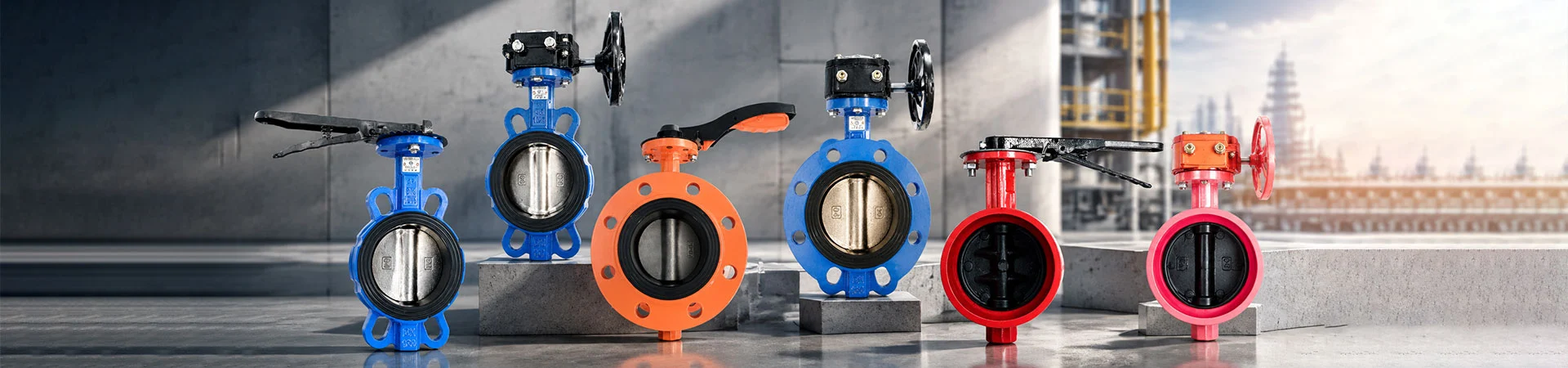
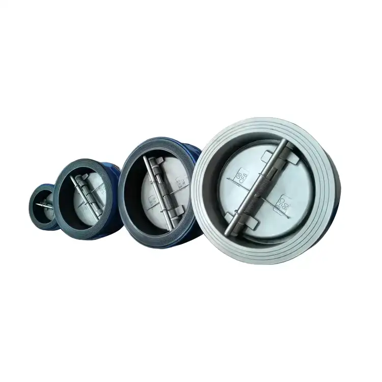
Wafer Check Valve
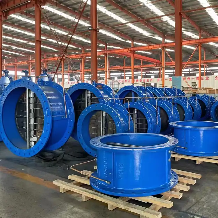
Liangfa supplies wafer check valves designed to prevent reverse flow in water supply, fire protection, HVAC, and selected industrial pipeline systems. Available in compact wafer-style configurations with ductile iron, carbon steel, and stainless steel body options, our valves offer different disc structures and sealing materials to meet specific pressure, temperature, and media requirements.
At Liangfa, we supply wafer-style check valves for industrial and commercial pipeline systems where backflow prevention, compact installation, and dependable operation are important. Our Wafer Check Valve range includes different body materials, disc structures, and sealing options to accommodate water supply, fire protection, HVAC, oil transfer, and selected chemical applications.
Product Specifications
| Product Name | Wafer Check Valve |
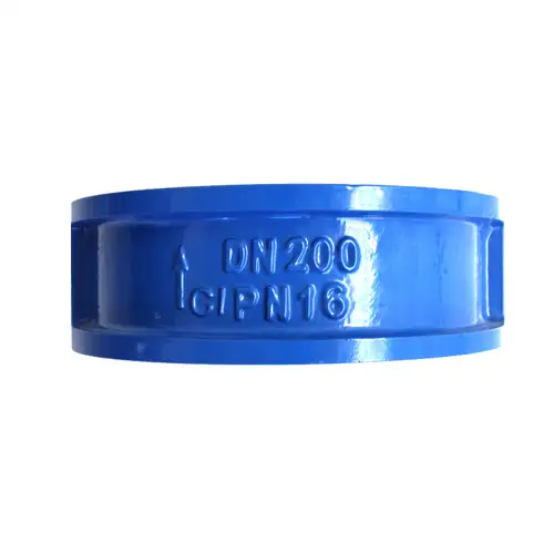
| Available Nominal Size | DN40–DN1200 for the listed product range; confirm the specific model and size before ordering |
| Connection | Wafer type, installed between pipeline flanges |
| Pressure Ratings | PN10, PN16, 150LB, 5K, 10K, 16K; other ratings are subject to model confirmation |
| Temperature Range | -10°C to 100°C for the listed configuration; actual limits depend on body, seat, and spring materials |
| Coating | Fusion-bonded epoxy coating in accordance with ANSI/AWWA C550, where specified |
| Design Reference | JB/T 8937, subject to the selected model and applicable requirements |
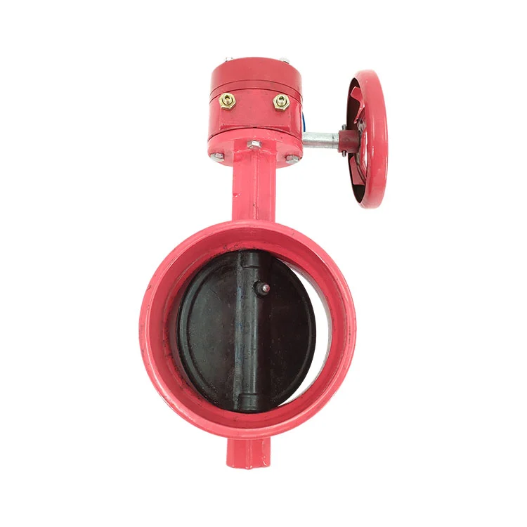
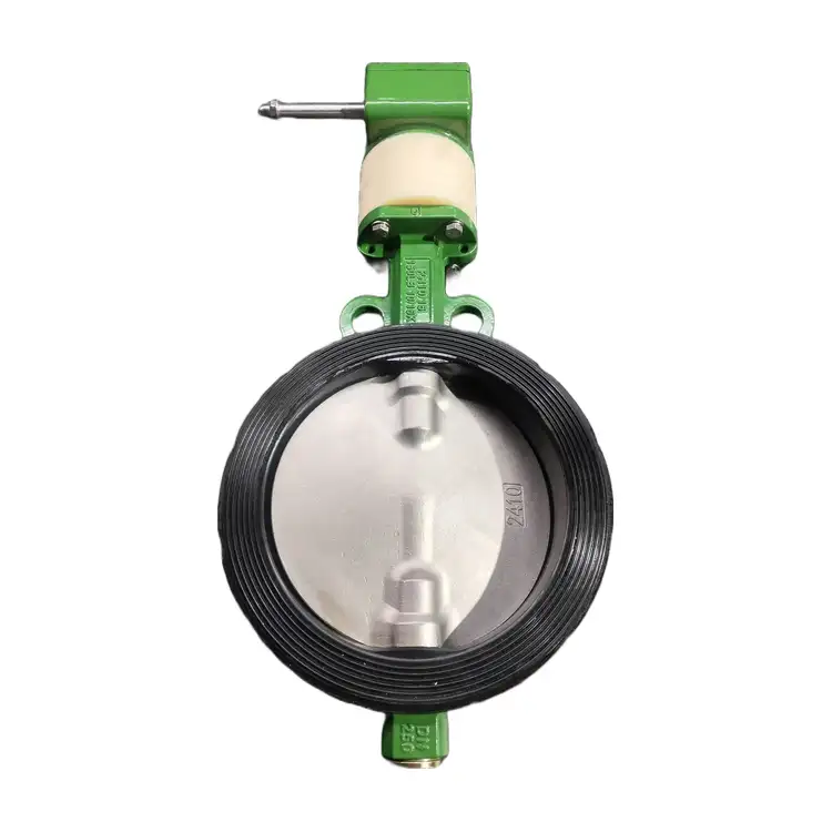
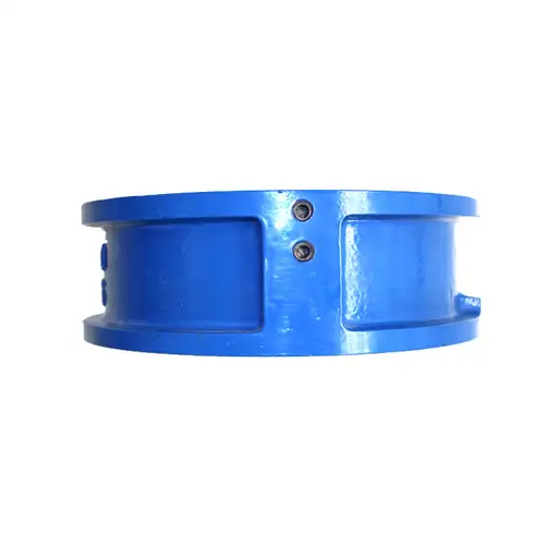
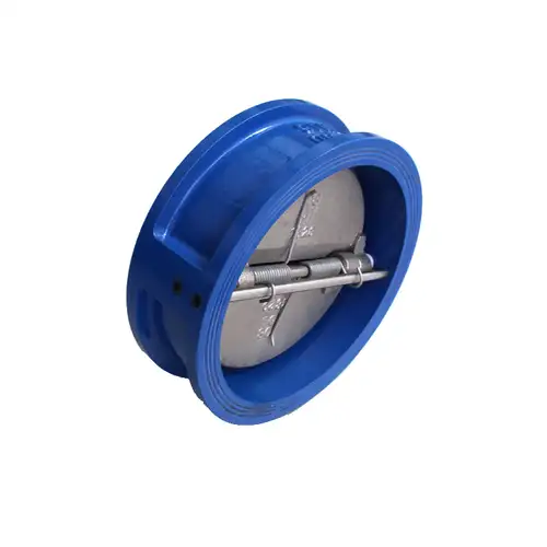
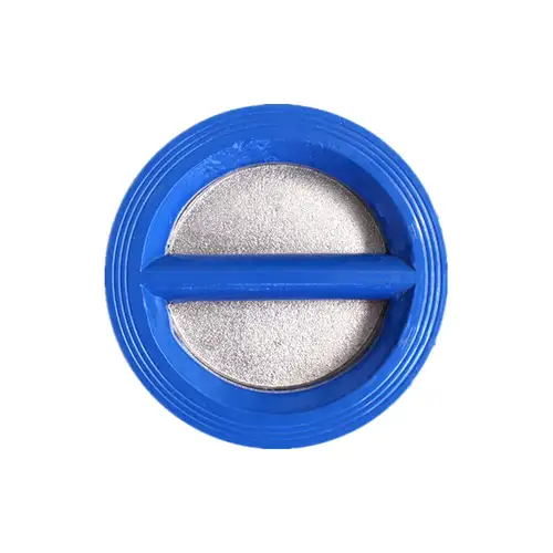
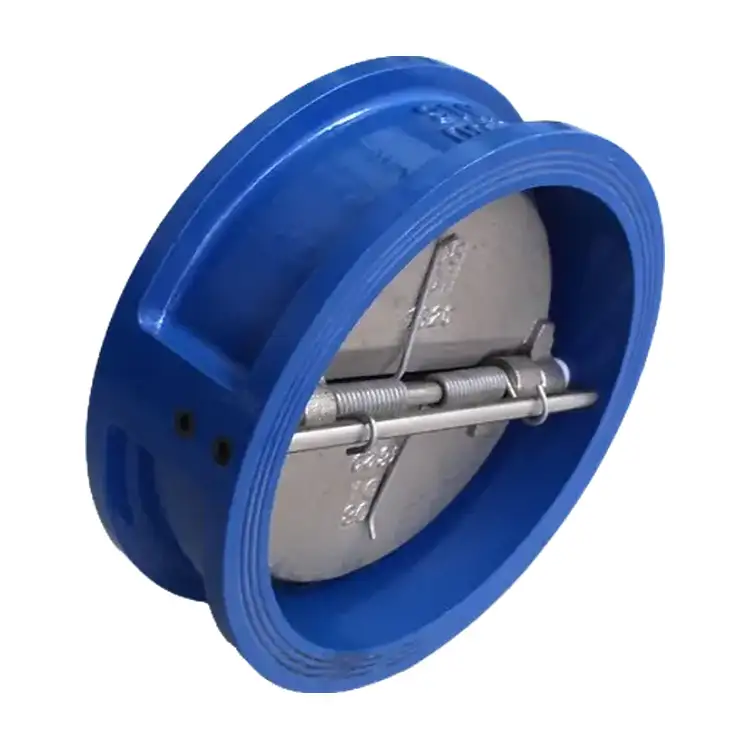
A wafer-style body fits between two mating pipe flanges, reducing installation length compared with many flanged valve designs. Depending on the selected model, the internal mechanism uses a single lifting disc or two spring-assisted discs. Forward flow opens the valve, while reverse pressure and the closing mechanism return the disc or discs toward the seat to restrict backflow.
The compact construction is useful where pipe space and equipment weight matter. However, opening pressure, pressure loss, closure response, and allowable leakage vary with the valve structure, size, spring design, and sealing material. We recommend confirming these details against the actual pipeline conditions instead of selecting by nominal diameter alone.
Choose the Right Internal Design
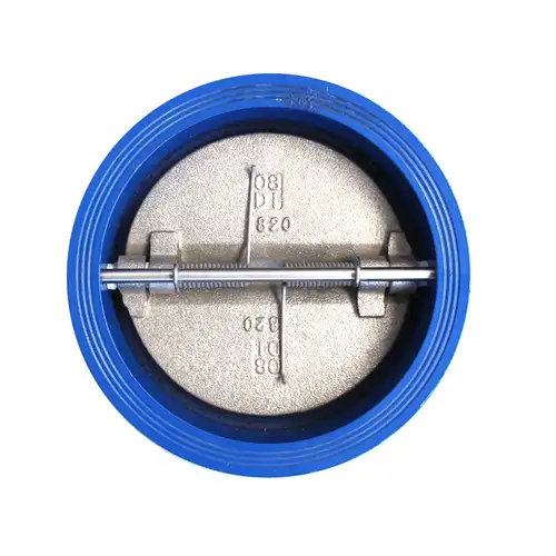
Different check valve structures respond differently to flow, pressure, and installation conditions. We help buyers compare the available designs before finalizing a model.
Single-Disc Lift Design
The H71 lift-type design uses a single disc that moves along its guiding structure. It is generally considered for smaller pipelines carrying relatively clean media. Its flow resistance and closure characteristics should be checked carefully where pressure loss or water hammer is a concern.
Spring-Assisted Dual-Disc Design
The H76 double-disc design uses two semicircular discs and spring assemblies. Its short disc travel and compact body can provide a quicker closing response than some conventional check valve designs. It is commonly considered for pump outlets, water circulation, and other applications where backflow control and installation space are important.
Soft-Seated or Metal-Seated Options
Soft seats, such as EPDM or NBR, can provide tight shutoff when the elastomer is compatible with the medium, temperature, pressure, and required leakage class. Metal seats are considered for selected higher-temperature or more demanding industrial services, but they may permit some leakage. The appropriate choice depends on the specified performance requirements.
| Design | Typical Characteristics | Potential Applications | Points to Check |
| H71 single-disc lift type | Single guided disc; generally suited to smaller sizes | Clean water, selected oil or gas services where the design is approved | Pressure loss, opening differential pressure, and closure response |
| H76 dual-disc metal seat | Compact body with spring-assisted disc closure | Selected water, oil, and industrial services | Metal-seat leakage requirements, medium compatibility, and temperature rating |
| H77X dual-disc soft seat | Elastomer sealing surface for tight shutoff in compatible service | Clean water, HVAC circulation, and selected fire-water systems | Seat compatibility, temperature limit, and required leakage class |
Model codes and availability can vary by manufacturer and configuration. Please provide the required size and operating conditions so we can confirm the exact construction rather than relying on a model code alone.
Materials for Different Media
Selecting a suitable material combination is essential for service life and sealing performance. The body, disc, stem, spring, and seat do not necessarily need to use the same material; each should be evaluated for corrosion, temperature, mechanical loading, and compatibility with the process fluid.
| Component | Available Materials |
| Body | Cast Iron, Ductile Iron, WCB Carbon Steel, SS304, SS316 |
| Disc | Ductile Iron, SS304, SS316, SS2507, SS1.4529 |
| Stem | 410 Stainless Steel, SS304, SS316, SS2507, SS1.4529 |
| Seat Liner | EPDM, NBR, PTFE, FKM (Viton) |
| Lever, where applicable | Ductile Iron, SS304 |
| Fasteners | Galvanized Carbon Steel, SS304, SS316 |
For Clean Water and Fire-Water Systems
Ductile iron bodies with a compatible protective coating and EPDM seating are commonly considered for clean water and fire-water applications. The final selection should meet the system's pressure, temperature, approval, and leakage requirements.
For Oil and Hydrocarbon Services
WCB carbon steel and oil-compatible sealing materials may be suitable for selected oil services. NBR is often considered for compatible oil applications, while EPDM is generally unsuitable for mineral oils. Confirm the fluid composition and temperature before selecting the seat.
For Corrosive or Chloride-Containing Media
Stainless steel grades and higher-alloy components may be considered for corrosive service, but no single grade is suitable for every chemical or seawater condition. Chloride concentration, temperature, flow conditions, and crevice exposure all affect corrosion risk. We recommend a material review for seawater and chemical applications, including the spring and other internal parts.
For Higher-Temperature Operation
The listed product configuration has a stated operating range of -10°C to 100°C. Other material combinations may have different limits, but they must be verified for the complete valve assembly. Do not apply a body material's maximum temperature rating to the seat or spring without checking the manufacturer's approved configuration.
Pressure and Size Selection
Correct sizing helps prevent excessive pressure loss, unstable disc movement, and premature wear. When requesting a quotation, we recommend confirming the following parameters.
- Nominal diameter: Match the valve size to the pipeline design. Any size reduction or expansion should be evaluated hydraulically.
- Working pressure: Specify normal and maximum operating pressure, including possible surge conditions. The valve's pressure rating must be suitable for the system at its operating temperature.
- Flange standard: Confirm the pipe flange standard, pressure class, facing, and dimensions. A wafer valve has no integral flanges, so compatibility with both mating flanges is essential.
- Flow rate: Provide normal and maximum flow rates where available. Flow velocity and the valve's opening characteristics affect pressure loss and disc stability.
- Medium: Identify the fluid, concentration, temperature, viscosity, and presence of solids or fibers.
- Leakage requirement: State whether tight shutoff is essential and identify any applicable leakage standard or acceptance criterion.
Pressure classes such as PN10, PN16, Class 150, and other ratings are not automatically interchangeable. We verify the selected valve rating and mating flange requirements against the applicable dimensional and pressure standards before confirming an order.
Where These Valves Are Used
Water Supply and Pump Stations
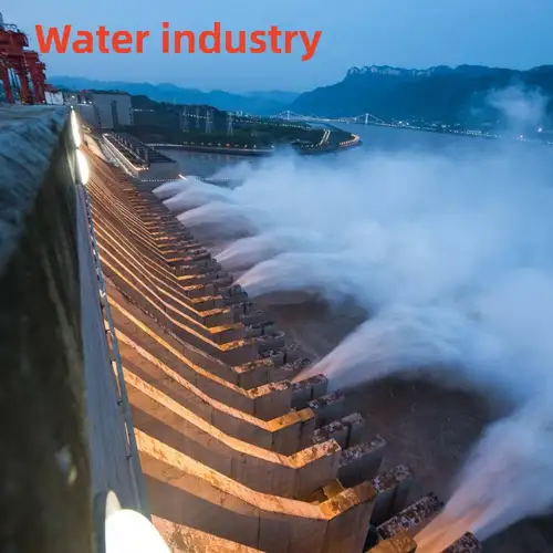
Installed in suitable pump discharge and water distribution lines, the valve helps limit reverse flow when the pump stops. Correct sizing and placement are important to control closure behavior and pressure transients.
Fire-Protection Pipe Networks
Wafer check valves can be considered for compatible fire-water piping where the selected product meets project specifications and any required approvals. Confirm the required listing, pressure rating, seat material, and installation rules for the jurisdiction.
HVAC and Cooling-Water Circuits
In chilled-water and cooling-water systems, the valve helps prevent unwanted reverse circulation between pumps and equipment. The body and seat materials should be suitable for the system fluid and operating temperature.
Industrial Oil and Process Lines
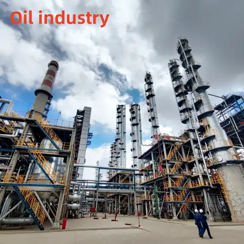
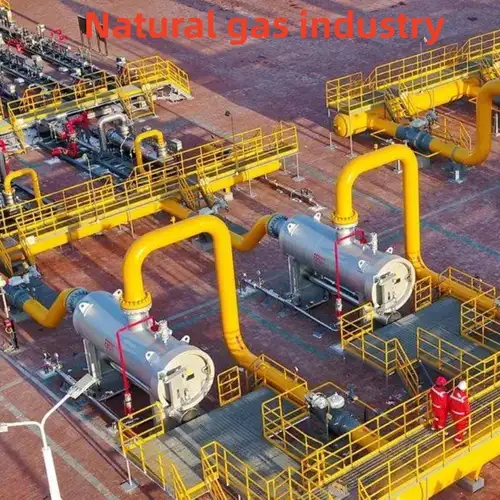
Selected models can serve oil and process-fluid lines when the body, disc, spring, and seal are compatible with the medium. For hot oil, solvents, or corrosive chemicals, confirm material compatibility and allowable leakage before purchase.
Coastal and Seawater Systems
Seawater and chloride-rich applications require careful corrosion assessment. Body material alone is not enough: disc, spring, fasteners, and sealing components must also be reviewed. We can help evaluate the material combination against the stated water chemistry and service conditions.
Clean Process Water in Food and Pharmaceutical Facilities
Stainless steel options may be considered for suitable clean-process-water systems. If the application requires hygienic design, documented material traceability, or sanitary approvals, specify those requirements in advance; a stainless steel body alone does not establish hygienic compliance.


Installation Checks Before Start-Up
A correctly selected valve can still perform poorly if the pipeline is contaminated, the flange faces are misaligned, or the flow direction is incorrect. Our recommended checks include:
- Inspect the delivered valve. Verify the model, size, pressure rating, materials, flow arrow, and required documentation against the purchase order.
- Clean the pipeline. Remove welding slag, rust, sand, and other debris that could obstruct disc movement or damage the seat.
- Check flange compatibility. Confirm flange dimensions, facing, gasket arrangement, and bolt length. Center the valve carefully between the two flanges.
- Follow the flow arrow. Install the valve in the intended direction and follow the installation instructions for the specific model.
- Verify mounting orientation. Horizontal and vertical installation may be permitted for spring-assisted designs, but vertical downward flow is not suitable for every model. Confirm the manufacturer's instructions before installation.
- Tighten evenly. Tighten flange bolts in a diagonal sequence to help prevent uneven loading or damage to the valve body and seat.
- Commission gradually. Fill and pressurize the pipeline in a controlled manner, check for external leakage, and observe valve response under the specified operating conditions.
Do not assume a spring-assisted check valve will eliminate water hammer. Closure behavior depends on flow velocity, pump characteristics, pipeline length, pressure, and system dynamics. For systems with severe surge risk, a hydraulic transient assessment may be needed to determine whether additional surge-control equipment is required.
Maintenance and Troubleshooting
Inspection frequency should be based on the medium, operating severity, service history, and consequences of failure. Corrosive fluids, high temperatures, frequent cycling, and contaminated media can increase maintenance needs.
| Observed Issue | Possible Cause | Recommended Check |
| Backflow after pump shutdown | Debris on the seat, worn sealing surface, damaged or fatigued spring | Isolate the system, depressurize, and inspect the disc, seat, and spring |
| Unexpected pressure loss | Disc not opening fully, obstruction, incorrect sizing, or excessive flow velocity | Check the internal mechanism and review flow and sizing data |
| External leakage at the flange | Damaged gasket, uneven bolt loading, or incompatible flange faces | Depressurize and inspect the flange joint and gasket arrangement |
| Knocking or unstable operation | Disc oscillation, unsuitable flow conditions, or incorrect valve selection | Review flow rate, pipeline layout, and valve operating characteristics |
| Corrosion or spring damage | Material incompatibility with the medium or temperature | Reassess material selection and inspect affected internal parts |
Before any disassembly, isolate the valve, release system pressure, and drain the fluid safely. Use appropriate lockout/tagout procedures and personal protective equipment. Replace damaged seats, discs, or springs with compatible parts and perform the required checks before returning the pipeline to service.
Manufacturing and Delivery
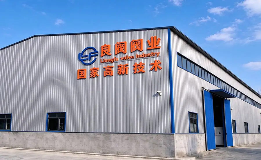
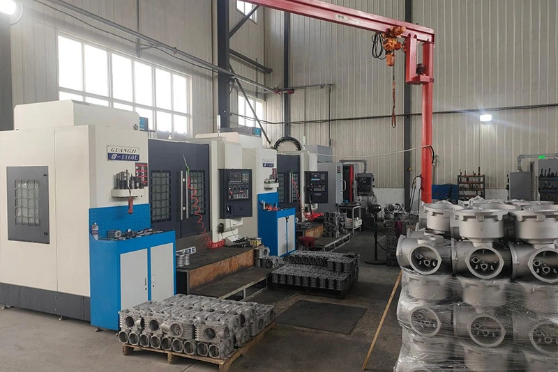
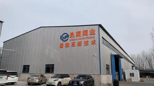
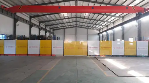
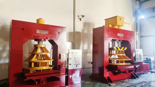
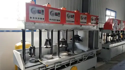
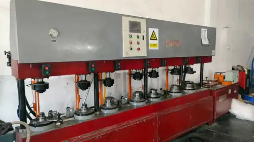
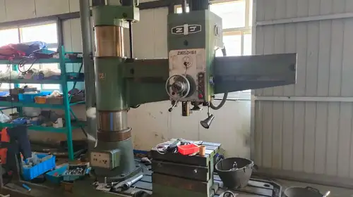
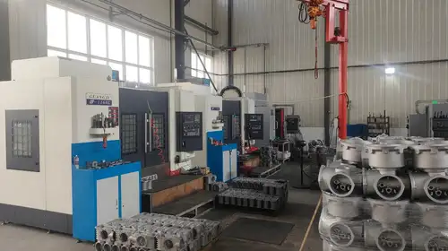
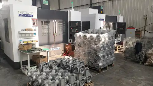
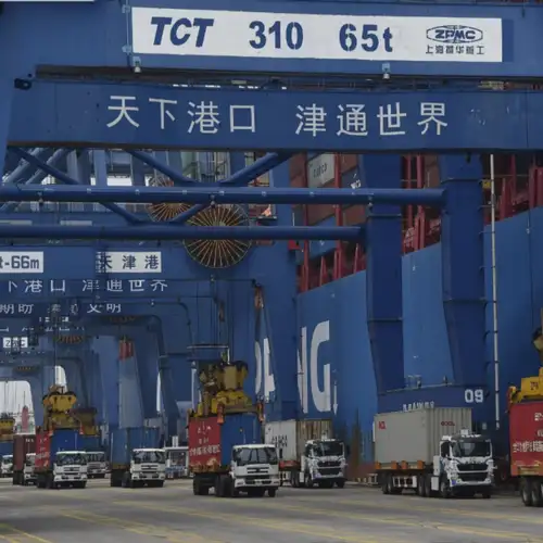
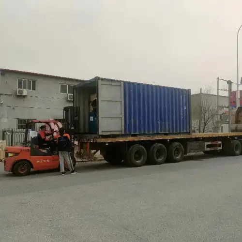
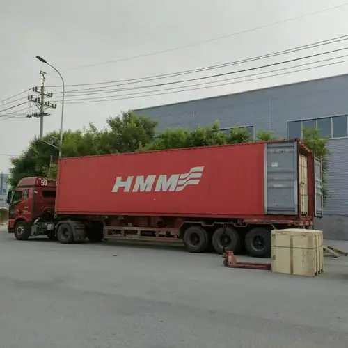
Liangfa supports customers through product selection, specification confirmation, production inspection, and export delivery. Our service can include technical drawings, material options, quotation support, inspection documentation, and export packaging, subject to the agreed order requirements.
Packaging and Shipment
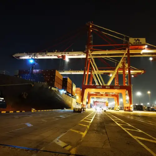
We arrange packaging and shipment according to the order, destination, and transport method. Export documentation and inspection records can be prepared as agreed. Customers should confirm packaging requirements, shipping marks, delivery schedule, and required certificates before production is finalized.
Support from Selection to After-Sales
Before Ordering
We help review the medium, nominal size, pressure, temperature, flange standard, material requirements, and installation conditions. Drawings, technical details, and quotation information can be supplied for the selected configuration.
During Production and Shipment
We coordinate production updates and agreed inspection requirements. Inspection reports, material documents, and export paperwork are available when included in the order scope.
After Delivery
We provide technical guidance for installation and maintenance and can discuss replacement parts for the supplied model. Our stated warranty period is 12 months from shipment, subject to the agreed warranty terms. For quality-related feedback, our service target is to respond within 24 working hours.
Frequently Asked Questions
What information should I provide to receive an accurate quotation?
Please provide the nominal diameter, working and maximum pressure, operating temperature, medium composition, required body and seat materials, flange standard, quantity, destination, and any project-specific approvals. Flow rate and leakage requirements are also helpful for technical review.
Can a wafer check valve be installed between any two pipeline flanges?
No. The valve must match the flange dimensions, pressure class, facing, and installation space. Bolt length and gasket arrangement must also be checked because the wafer body is clamped between the mating flanges.
Is a soft seat always better than a metal seat?
Not in every application. A compatible elastomer seat can provide tight shutoff for suitable fluids and temperatures, while a metal seat may be preferable for certain higher-temperature or demanding industrial services. The correct choice depends on fluid compatibility, temperature, pressure, and allowable leakage.
Can this valve handle slurry or wastewater containing large particles?
Spring-assisted wafer designs are generally not recommended for media containing large quantities of hard solids, abrasive particles, or long fibers. These materials can obstruct disc movement and damage the sealing surface. For such conditions, we recommend reviewing alternative check valve structures designed for solids handling.
Will the spring-assisted design completely prevent water hammer?
No check valve alone can guarantee that water hammer will be eliminated. Spring-assisted closure can help reduce reverse-flow effects in suitable systems, but the result depends on pipeline dynamics, flow velocity, pump shutdown behavior, and valve selection. Severe surge conditions may require additional engineering measures.
What quality documents and customization can be requested?
Depending on the product configuration and order agreement, we can discuss inspection records, material documentation, drawings, special material combinations, pressure-rating requirements, and export packaging. Please identify mandatory standards or approvals before ordering so they can be checked during quotation.
Related Category
Send Inquiry
Contact Info
-
Address
No. 2 Taikang Road, Xiditou Town, Beichen District, Tianjin City, China
-
Tel
-
Email
If you have any inquiry about a quotation or cooperation, please feel free to email or use the following inquiry form. Our sales representative will contact you within 24 hours.
News Recommendations