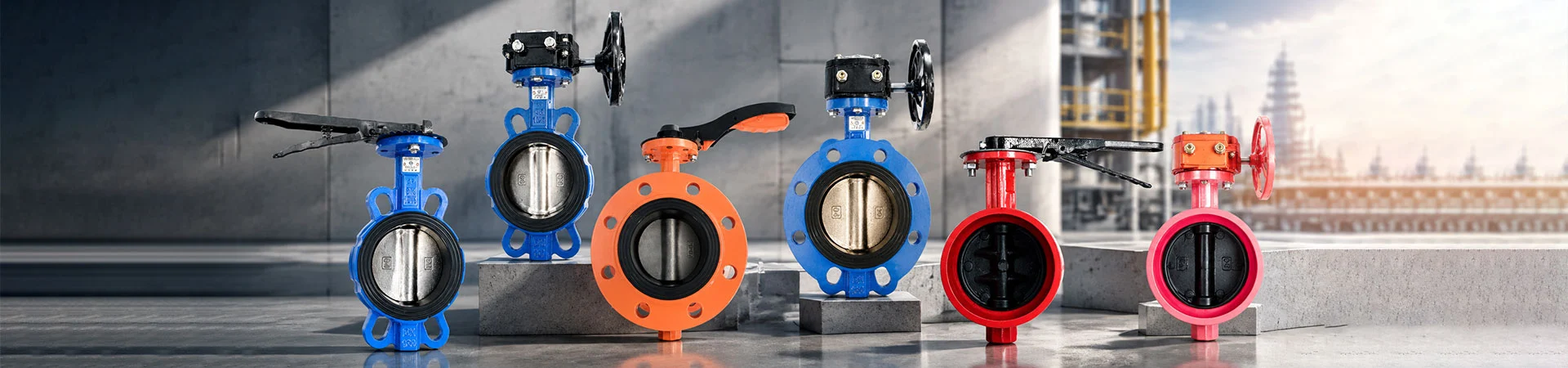
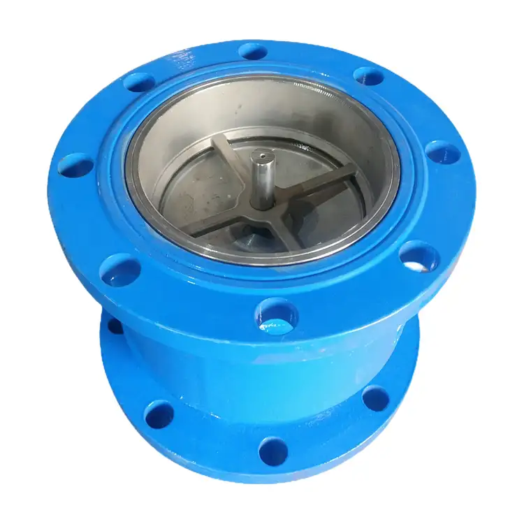
Silent Check Valve
Our Silent Check Valve is designed to prevent reverse flow in water supply and circulation systems while helping reduce water hammer and operating noise when pumps stop. At Liangfa, we provide check valve solutions for municipal water supply, high-rise buildings, HVAC systems, fire protection, and industrial water circulation.
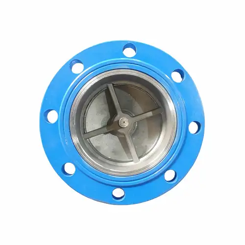
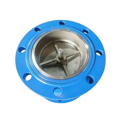
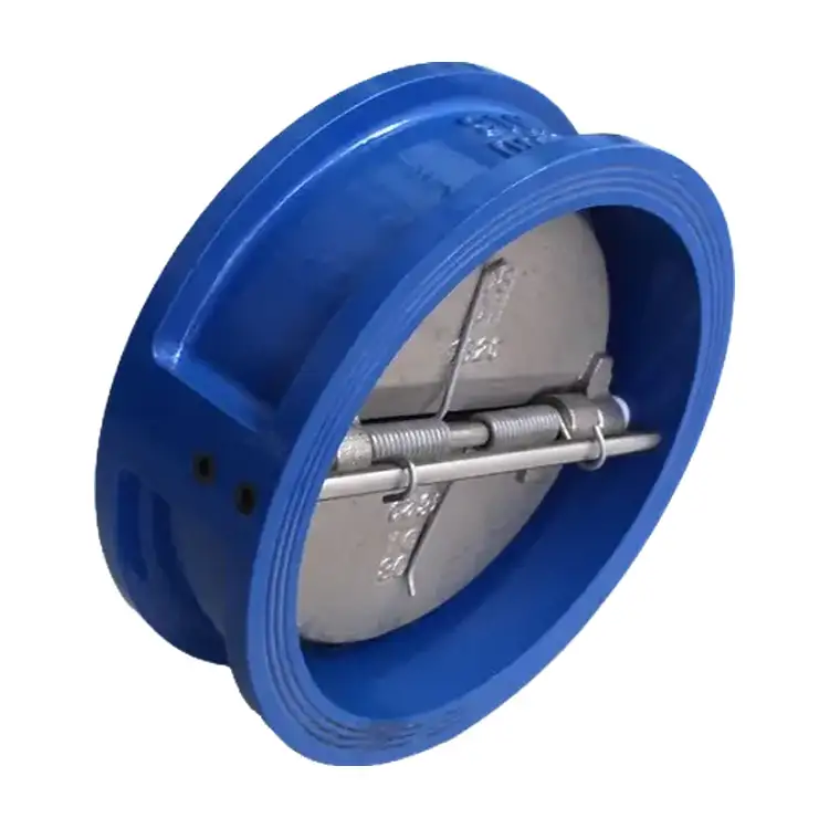
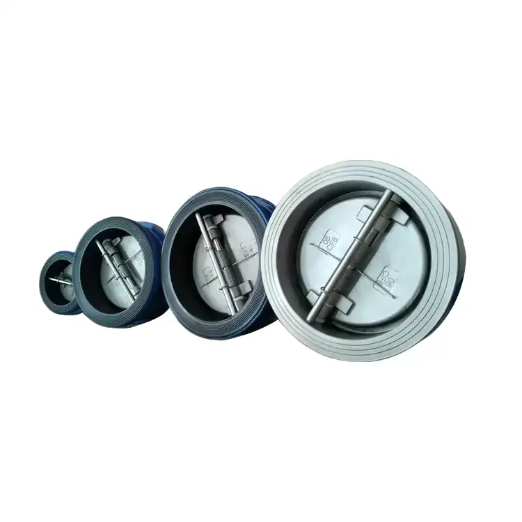
At Liangfa, we supply silent check valves for water pipeline systems that require reliable backflow prevention, reduced operating noise, and stable pump protection. Our HC41X-10/16Q model features a spring-guided disc, streamlined flow passage, and soft sealing structure for efficient operation in clean-water applications.
Available material options, wafer-style configurations, and multiple pressure ratings help us support building water supply, fire protection, HVAC circulation, and municipal water projects. As a high-tech enterprise, we focus on practical valve engineering and technical selection support to help customers match each valve to its actual operating conditions.
How the Spring Mechanism Works
A silent check valve prevents reverse flow without requiring an external power supply or manual operation. Our HC41X design uses the pressure of the flowing medium to open the disc against a spring. When the pump stops and forward pressure decreases, the spring assists the disc in returning to its seat before substantial reverse flow develops.
Short-Stroke Closing
The centrally guided disc moves along a controlled path inside the valve body. Its short travel distance allows a quick response to changes in flow, while the spring helps the disc reseat promptly. This design reduces metal-to-metal impact noise and helps limit the pressure fluctuations associated with pump shutdown in suitable systems.
Soft Sealing and Smooth Flow
Our design uses a rubber sealing element to provide close contact between the disc and seat. The streamlined flow passage supports smooth forward flow and helps limit pressure loss. Actual leakage performance and head loss depend on the selected size, material combination, operating pressure, and test conditions.
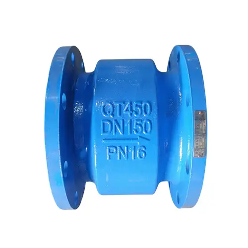
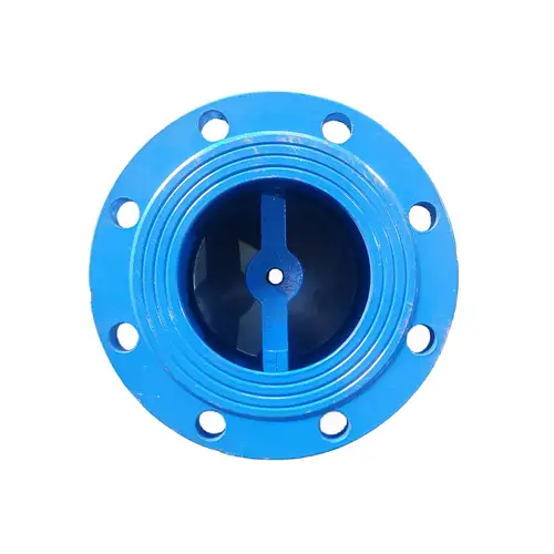
Product Specifications
We offer different sizes, pressure ratings, and material combinations for compatible water systems. The following table summarizes the supplied product information. Because the general product range and the HC41X model range differ in the source specifications, we recommend confirming the exact model, dimensions, and rating before ordering.
| Product Name | Silent Check Valve |
| Model | HC41X-10/16Q |
| General Listed Size Range | DN40–DN1200; confirm the available range for the selected model |
| HC41X Size Range in Technical Description | DN40–DN600 |
| Connection | Wafer connection listed in the product table; confirm the connection and face-to-face dimensions for the specific model |
| Pressure Ratings | PN10, PN16, 150LB, 5K, 10K, 16K, subject to model availability |
| General Listed Temperature Range | -10°C to 100°C; confirm the permitted range for the selected seal and model |
| Coating | Fusion-bonded epoxy coating in accordance with ANSI/AWWA C550, where specified |
| Operating Principle | Spring-assisted automatic closure |
| Typical Medium | Clean water and compatible water-based circulation media |
Materials for Different Water Systems
Material selection affects corrosion resistance, sealing performance, temperature capability, and service life. We can review the working medium and operating conditions to help customers choose a suitable combination from the available materials.
Valve Body and Disc
Available body materials include cast iron, ductile iron, WCB carbon steel, SS304, and SS316. Disc options include ductile iron, SS304, SS316, SS2507, and SS1.4529. Ductile iron is commonly considered for general water supply applications, while stainless steel may be appropriate for certain corrosive environments.
Seals and Springs
Available seat liner materials include EPDM, NBR, PTFE, and FKM (Viton). NBR may be suitable for compatible cold-water applications, while EPDM is often considered for hot-water and HVAC circulation. The permitted temperature range depends on the specific compound, pressure, and medium.
Stainless steel springs are used to support repeated opening and closing. Spring material and preload should be selected according to the medium, available differential pressure, and required closing response. For chloride-rich or seawater environments, corrosion resistance must be assessed for the complete assembly rather than the spring alone.
| Component | Available Materials | Selection Consideration |
| Body | Cast Iron, Ductile Iron, WCB, SS304, SS316 | Pressure, corrosion resistance, and project requirements |
| Disc | Ductile Iron, SS304, SS316, SS2507, SS1.4529 | Medium compatibility and mechanical requirements |
| Stem or Guide Components | 410SS, SS304, SS316, SS2507, SS1.4529 | Wear resistance and corrosion exposure |
| Seat Liner | EPDM, NBR, PTFE, FKM (Viton) | Temperature, chemical compatibility, and sealing requirements |
| Lever, Where Applicable | Ductile Iron, SS304 | Confirm compatibility with the selected structure |
| Fasteners | Galvanized Carbon Steel, SS304, SS316 | Corrosion conditions and connection requirements |
How to Select the Right Model
Before purchasing, we recommend checking the system pressure, required flow rate, medium, temperature, installation orientation, and potential water hammer severity. A valve that fits the nominal pipe size may still be unsuitable if its spring resistance, flow capacity, or material combination does not match the application.
Check the Pipe Diameter and Flow Rate
The nominal diameter should be selected according to the pipeline design flow and acceptable pressure loss. The pump outlet size is a useful reference, but the main pipeline diameter, reducer arrangement, and actual operating flow must also be considered.
The supplied selection notes suggest a flow velocity of approximately 0.8–2.0 m/s as a starting range. Actual acceptable velocity depends on the system design and valve performance curve. Excessive velocity can increase pressure loss and wear, while insufficient flow may prevent the disc from opening steadily against the spring.
Match Pressure and Temperature
The selected pressure rating must accommodate the maximum operating pressure and any relevant transient pressure. PN10 and PN16 are listed options, but the correct rating depends on the complete system design and the available model.
The product table lists a general temperature range of -10°C to 100°C, while the detailed selection notes specify different limits for NBR and EPDM. We recommend confirming the actual seal compound, temperature rating, and suitability for the intended medium before finalizing an order.
Consider Spring Preload
Spring preload affects how readily the disc opens and how quickly it returns to the seat. A spring that is too strong for the available differential pressure may restrict opening, while an unsuitable spring can contribute to vibration or unstable operation. We recommend confirming spring specifications against the pump performance and expected flow conditions rather than changing the spring without technical review.
Confirm the Installation Direction
The supplied HC41X technical description permits horizontal installation and vertical installation with upward flow. Vertical downward flow is not recommended. The flow arrow on the valve body must match the direction of the medium, and the installed valve should remain accessible for inspection and maintenance.
Where This Valve Works Best
Our product is intended primarily for clean-water systems where automatic backflow prevention, reduced closing noise, and compact installation are important. The following examples help clarify where this design may be appropriate and where another valve structure should be considered.
Building Booster Pumps
In residential towers, hotels, hospitals, and commercial buildings, pump shutdown can cause reverse flow and unwanted noise in the pump room. A properly selected silent check valve helps limit reverse flow and supports stable pressure retention in compatible clean-water systems.
Fire Water Pipelines
The valve can be considered for compatible fire-water pump discharge lines where the design requires automatic backflow prevention and soft seating. Customers should verify the applicable fire system specifications, pressure rating, connection type, and acceptance requirements before using the valve in a fire protection project.
HVAC Circulation
In chilled-water, cooling-water, and compatible heating-water circuits, the valve can prevent reverse flow when a circulation pump stops. Seal selection must account for the operating temperature and any water-treatment chemicals present in the system.
Municipal and Industrial Clean Water
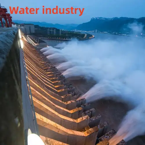
The valve may be used in suitable booster stations, water treatment plant clean-water lines, and industrial cooling circuits. For large-diameter, long-distance pipelines with substantial transient pressure, we recommend evaluating a slow-closing or hydraulic buffering check valve instead.




When to Consider Another Valve
A spring-assisted check valve is not the best solution for every pipeline. We help customers assess the limitations before choosing a model, especially when the system has demanding transient-pressure conditions or poor water quality.
| Operating Condition | Recommended Approach | Reason |
| Short pump discharge lines with clean water | Evaluate the HC41X silent check valve | Quick spring-assisted closure and reduced closing impact noise |
| Long-distance pipelines with severe water hammer | Evaluate a slow-closing check valve | Hydraulic buffering can be designed to control the closing process |
| Raw sewage or water containing fibers and large particles | Evaluate a suitable rubber-flapper or solids-handling check valve | Particles can obstruct the guide mechanism or damage the soft seal |
| Large-diameter pipelines with high transient energy | Evaluate a suitable buffered check valve and perform transient analysis | Valve size and rapid spring closure alone may not control the pressure surge |
| Low-flow pump systems | Review differential pressure and spring selection | The disc may not open fully if the available flow force is insufficient |
A silent-closing mechanism can reduce impact noise, but it does not eliminate every form of water hammer. For long pipelines or systems with a history of pressure surges, we recommend evaluating pump characteristics, pipeline length, flow velocity, and transient pressure before selecting the valve.
Installation and Maintenance
Correct installation helps maintain stable disc movement and sealing performance. Our recommended procedures should be checked against the approved model drawings and project requirements before work begins.
Prepare the Pipeline
Flush the pipeline to remove welding slag, rust, grit, and other debris before installation. A suitable upstream strainer may be used where the system design permits it. Excessive contamination can scratch the sealing surface or obstruct the disc guide.
Check the valve model, nominal diameter, pressure rating, material, and connection dimensions against the order documents. Inspect the body and sealing components for visible damage, and ensure that the disc moves freely according to the manufacturer's inspection procedure.
Install in the Correct Direction
Install the valve according to the flow arrow and the orientation permitted for the selected model. For the HC41X configuration described here, horizontal installation and vertical upward flow are specified. Do not assume that vertical downward flow is acceptable.
Align the valve with the pipeline without forcing the flanges or connected pipes into position. Use compatible gaskets and tighten fasteners evenly according to the connection requirements. Provide adequate pipe support, particularly for larger assemblies, and do not use the valve as a structural support.
Test After Installation
Fill the pipeline gradually and vent trapped air where required by the system design. Start the pump under controlled conditions and check for external leakage, abnormal vibration, unusual noise, and stable flow. After stopping the pump, observe whether the valve closes properly and whether the system maintains the expected pressure.
If the disc fails to open fully, vibrates continuously, or allows persistent backflow, investigate the differential pressure, spring specification, flow conditions, contamination, and guide assembly. Isolate and depressurize the system before opening the valve for inspection.
Routine Inspection
Inspect the valve and surrounding connections periodically for leakage, corrosion, abnormal noise, and pressure changes after pump shutdown. Clean upstream strainers as needed. During planned maintenance, check the seal for cuts, hardening, or deformation and inspect the spring and guide components for corrosion, wear, or restricted movement.
Any disassembly must be performed only after the line has been isolated, depressurized, and drained safely. After maintenance, carry out the required pressure and sealing checks before returning the valve to service.
Factory and Production
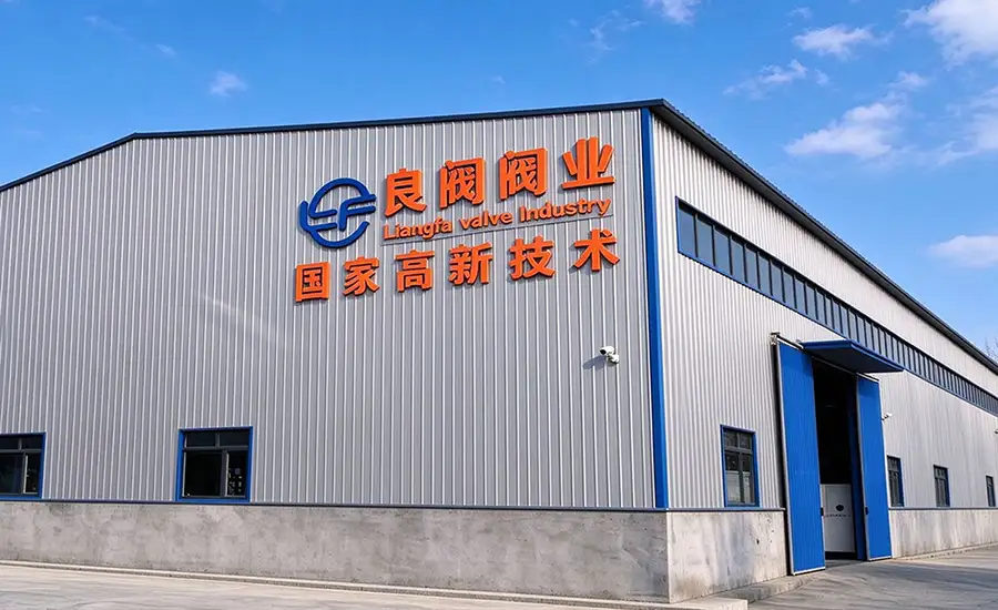
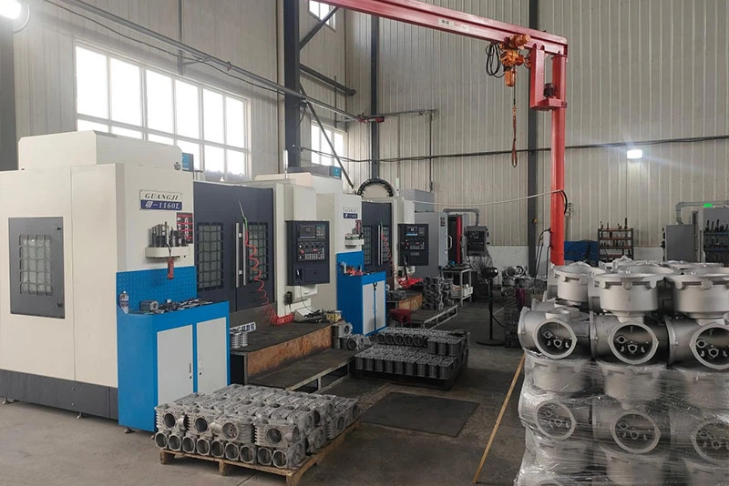
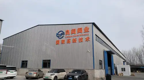
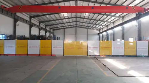
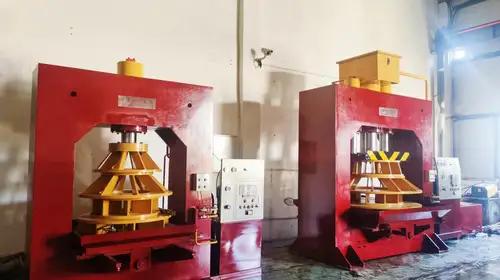
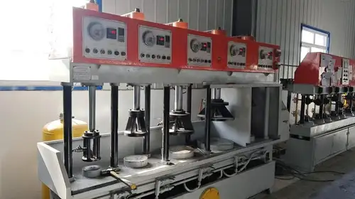
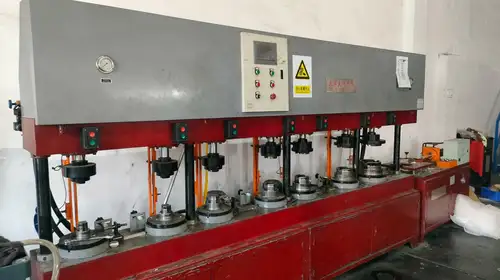
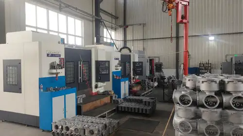
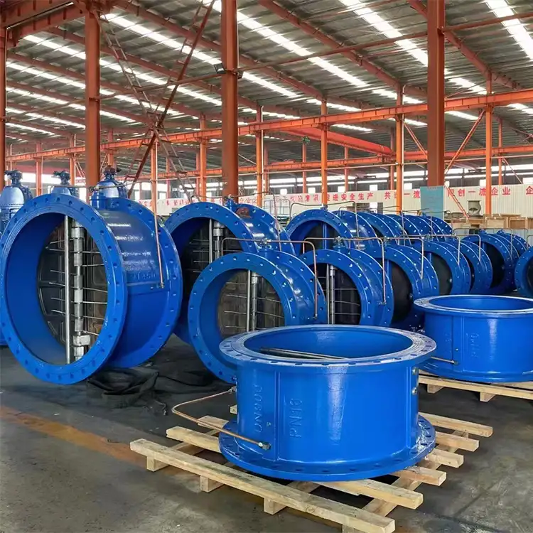
At Liangfa, we focus on manufacturing consistency and product verification for industrial valve applications. As a high-tech enterprise, we continue to develop our technical capabilities and support customers with product information, material selection, and project-specific requirements.
Inspection records, material documentation, product drawings, and other technical documents can be discussed according to the selected model and order requirements. Where a project specifies particular testing standards or inspection procedures, these should be confirmed before production.


Packaging and Delivery
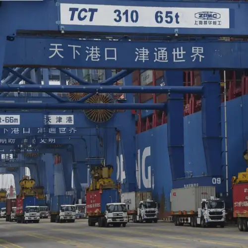
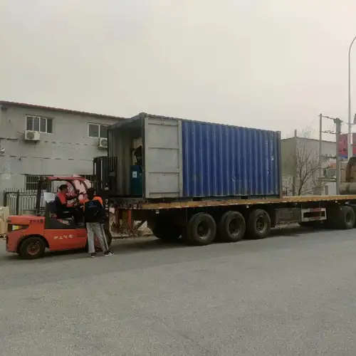
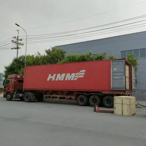
We coordinate export packaging and transportation according to order quantity, valve dimensions, destination, and delivery requirements. Packaging details and shipping documents can be confirmed before dispatch to help customers arrange receiving, storage, and installation.

Technical and After-Sales Support
Before Ordering
We provide technical consultation and model selection support based on pipe diameter, working pressure, medium, temperature, flow rate, and installation orientation. Customers can request available drawings, material options, technical parameters, and quotation details for review.
During Production and Shipment
We coordinate the agreed inspection requirements, production updates, export packaging, and shipping documentation. Applicable inspection reports and material certificates can be supplied where available and included in the agreed order requirements.
After Delivery
We can discuss compatible replacement parts, including seals, discs, and other model-specific components. Remote guidance is available for installation, troubleshooting, and routine maintenance. Our stated warranty period is 12 months from shipment, subject to the terms agreed in the sales contract.
Frequently Asked Questions
Does a silent check valve require electricity to operate?
No. The HC41X design described here operates through the pressure of the flowing medium and a spring-assisted closing mechanism. It does not require an external electrical actuator for normal check-valve operation.
Can the valve be installed vertically?
The supplied HC41X technical information permits vertical installation with upward flow as well as horizontal installation. Vertical downward flow is not recommended. Always confirm the orientation permitted by the exact model drawing before installation.
How do I choose between NBR and EPDM seals?
The choice depends on the medium, temperature, and chemical compatibility. NBR may suit certain cold-water applications, while EPDM is commonly used in compatible hot-water and HVAC systems. Because the supplied material notes contain different temperature limits, we recommend confirming the approved range for the actual seal compound before ordering.
Will this valve completely eliminate water hammer?
No valve should be assumed to eliminate every water hammer event. The spring-assisted quick-closing design helps limit reverse flow and closing impact in suitable systems, but severe pressure surges in long pipelines may require a slow-closing valve or a broader transient-control solution.
What causes the disc to vibrate or fail to open fully?
Possible causes include insufficient differential pressure, an unsuitable spring preload, flow conditions outside the recommended range, turbulence near elbows or reducers, or debris inside the guide assembly. We recommend checking the system operating data and installation arrangement before replacing components.
Can I use this valve for raw sewage or slurry?
We do not recommend the standard soft-seal, spring-guided configuration for media containing large amounts of solids, fibers, or abrasive particles. These contaminants can damage the seal or obstruct the guide mechanism. A valve designed specifically for solids-handling service should be evaluated instead.
Which documents should I request for a project order?
Depending on the project, useful documents include the product drawing, confirmed technical datasheet, material information, inspection records, pressure-test documentation, and applicable conformity documents. Please specify the required standards and inspection scope when requesting a quotation so we can confirm what is available for the selected model.
What information should I provide for a quotation?
Please provide the required DN size, pressure rating, medium, operating temperature, flow rate, connection dimensions, installation orientation, body and seal material preferences, quantity, and destination. If you are replacing an existing valve, a nameplate photograph and pipeline drawing can help us review compatibility.
Contact Liangfa to discuss your pipeline requirements and request a quotation. We can help you evaluate the appropriate model, material combination, and installation conditions for your clean-water application.
Related Category
Send Inquiry
Contact Info
-
Address
No. 2 Taikang Road, Xiditou Town, Beichen District, Tianjin City, China
-
Tel
-
Email
If you have any inquiry about a quotation or cooperation, please feel free to email or use the following inquiry form. Our sales representative will contact you within 24 hours.
News Recommendations