
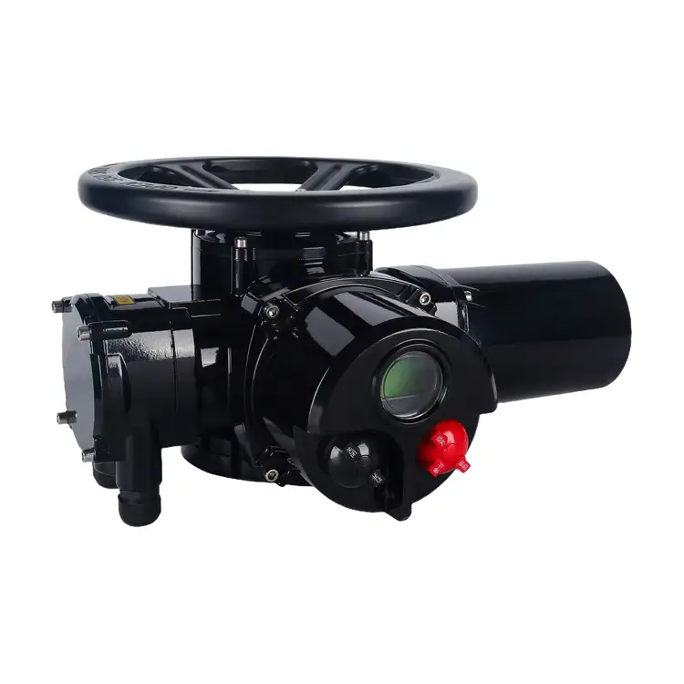
Intelligent Multi-turn Electric Actuator
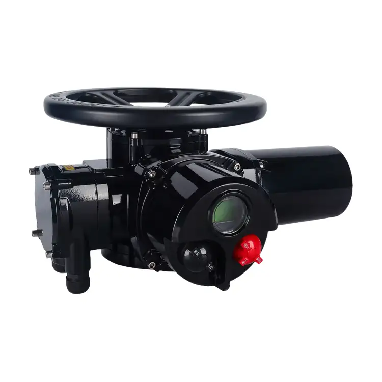
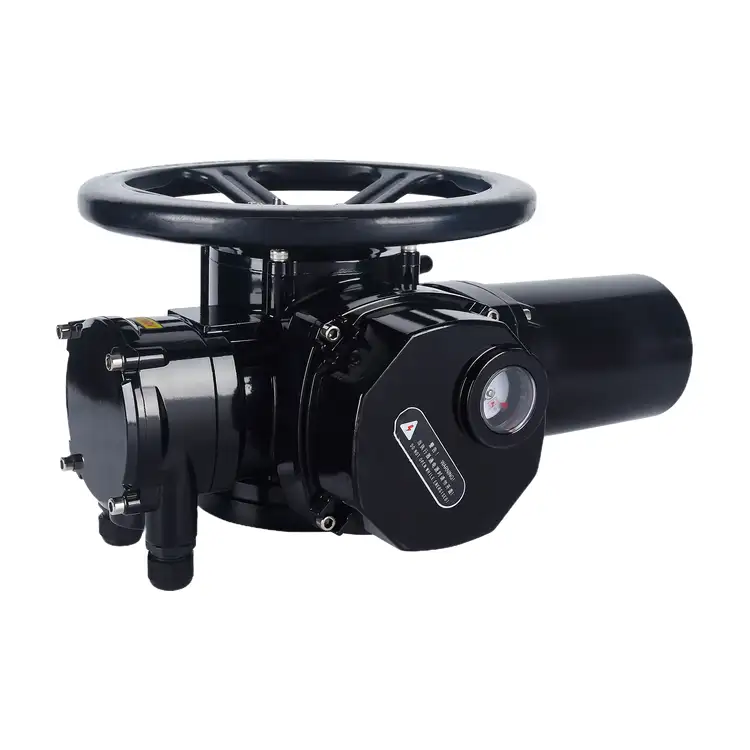
Liangfa supplies intelligent electric actuators for automated valve control in water treatment, power generation, heating, petrochemical processing, and other industrial applications. Designed for multi-turn valves, the Intelligent Multi-turn Electric Actuator combines absolute position detection, digital parameter setting, torque protection, and flexible control options to support reliable valve operation.
The Intelligent Multi-turn Electric Actuator is designed for gate valves, globe valves, plunger valves, and other compatible multi-turn valves. It supports automatic opening and closing, with a modulating option for applications that require adjustable valve positioning. Its ISO 5210 mounting interface helps simplify mechanical matching when the flange and thrust-base specifications are correctly selected.
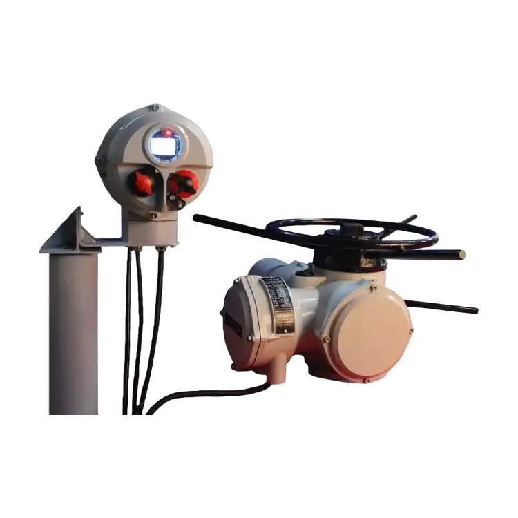
An integrated DSP controller and absolute encoder record valve-position information without relying on a battery-backed position memory system. The bilingual LCD displays operating status, valve opening, and fault information. Operators can configure parameters through the local keypad or optional infrared remote control without opening the control compartment, helping maintain enclosure protection during routine adjustment.
Available in on-off and modulating configurations, the unit supports AC380V three-phase power as standard, with AC220V single-phase available as an option. Modulating models accept a 4–20 mA command signal, with stated control accuracy of ≤±1% under specified conditions. Optional Modbus RTU, Profibus-DP, and HART interfaces support integration with compatible PLC and DCS systems.
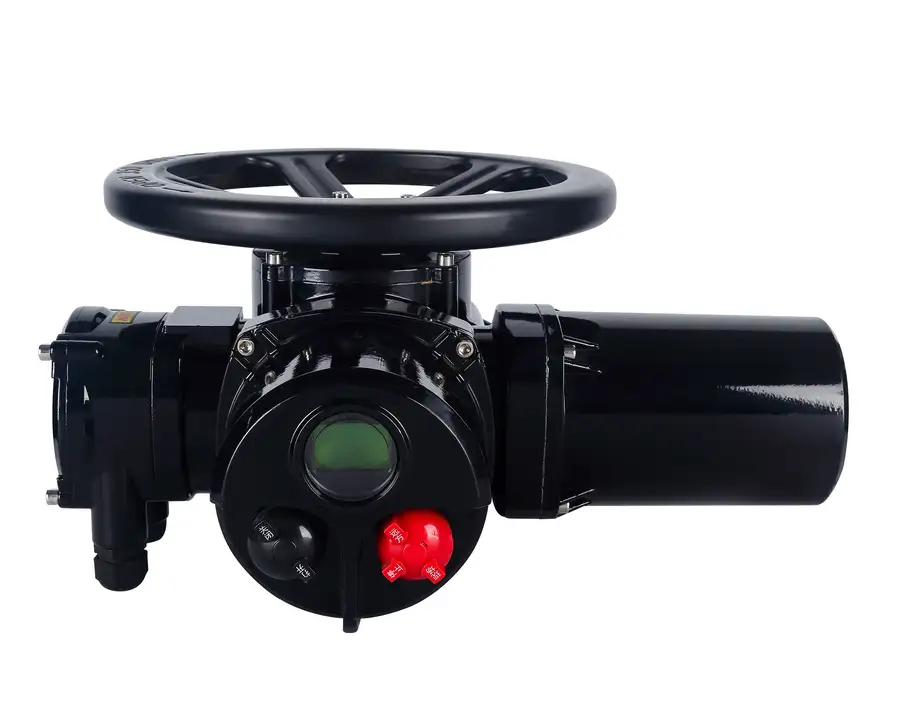
Technical Specifications
| Item | Specification |
|---|---|
| Product type | Intelligent multi-turn electric actuator |
| Mounting interface | ISO 5210 |
| Position detection | Absolute encoder |
| Main controller | DSP control chip |
| Display | Bilingual LCD |
| Control modes | On-off / modulating |
| Modulating signal | 4–20 mA input; 4–20 mA position feedback available by configuration |
| Modulating accuracy | ≤±1% under specified conditions; adjustable dead zone |
| Communication | Modbus RTU / Profibus-DP / HART optional |
| Power supply | AC380V three-phase standard; AC220V single-phase optional |
| Enclosure protection | IP55 standard; IP67 optional |
| Hazardous-area option | Ex d IIB T4 flameproof version, subject to the applicable certificate |
| Duty rating | S4 intermittent duty |
| Ambient temperature | -20°C to +60°C standard |
| Drive mechanism | Worm and wormwheel reduction with mechanical self-locking |
| Protection functions | Travel limit, over-torque, motor overheat, phase-loss and stall protection, subject to configuration |
Final specifications depend on the selected model and options. Please confirm rated torque, output speed, number of output rotations, flange size, feedback signals, and protection requirements before ordering.
Choose the Right Control Mode
On-Off Operation
The on-off version is intended for valves that operate between fully open and fully closed positions. It is suitable for pipeline isolation, water distribution, equipment inlets and outlets, and other applications that do not require continuous positioning. Open/close commands and limit-status feedback can be connected to a compatible control system according to the selected wiring configuration.
Modulating Control
For processes that require valve-position adjustment, the modulating version accepts a 4–20 mA command signal. Adjustable dead-zone settings help match the actuator response to the control loop. With compatible position feedback, the system can compare the commanded and actual valve positions to support flow or pressure regulation.
On-off and modulating versions use different control configurations. We recommend specifying the required operating mode when requesting a quotation rather than assuming an on-off model can be converted through a simple field adjustment. The S4 intermittent-duty rating must also be considered: applications involving frequent movement or extended modulation should be checked against the model's permitted operating frequency and duty limits.
Communication with PLC and DCS Systems
Depending on the control system, optional Modbus RTU, Profibus-DP, or HART communication can be specified. These interfaces support system integration, remote status monitoring, and access to available operating or fault information. Protocol compatibility, addressing, wiring, and supported data points should be confirmed with the selected actuator model and the customer's PLC or DCS.
Position Feedback and Equipment Protection
Absolute Position Detection
The absolute encoder stores valve-position information without the battery-backed memory approach used by some systems. After a power interruption, the controller can retain position information, reducing the need for routine position recovery. Correct installation and initial stroke calibration are still essential for accurate valve-position display.
Torque and Travel Protection
The controller can monitor operating conditions and stop the actuator when configured protection limits are reached. Travel-limit and over-torque functions help reduce the risk of driving a valve beyond its permitted travel or continuing to operate against a jammed stem. Motor-overheat, stall, and phase-loss protections provide additional safeguards where supported by the selected configuration.
Protection settings must match the actual valve and actuator ratings. A torque threshold set too low may cause unnecessary trips, while an excessively high setting can expose the valve stem, gearbox, or transmission components to damage. We recommend using the valve manufacturer's operating-torque data and commissioning instructions to determine appropriate settings.
Mechanical Drive and Manual Operation
The worm-and-wormwheel transmission provides reduction and mechanical self-locking characteristics that help maintain valve position under suitable operating conditions. Oil-bath lubrication supports the transmission, subject to the model's maintenance requirements. Where a handwheel and manual/electric changeover mechanism are included, operators can use manual operation when permitted by the equipment procedure and site safety rules.
Match the Actuator to Your Valve
Confirm Valve Type and Stem Travel
First, confirm that the valve is a multi-turn type. Gate valves, globe valves, plunger valves, and compatible knife-gate valves may be suitable when their torque, travel, and mounting requirements match the actuator. Butterfly and ball valves generally use quarter-turn actuation and should not be paired with a multi-turn actuator unless an engineered transmission arrangement has been specifically designed for the application.
Record the valve's nominal diameter, pressure rating, medium, temperature, maximum differential pressure, stem diameter, stem type, and total number of rotations required for full travel. DN alone is not enough to determine the correct actuator size.
Calculate the Required Torque
As an initial selection method, use the valve manufacturer's maximum operating torque and apply a suitable safety factor:
Required actuator torque = maximum valve operating torque × application safety factor.
A factor of approximately 1.3–1.5 may be a starting point for clean water under normal conditions. Sewage, sediment-laden media, scaling, high-temperature service, or valves with variable resistance may require a higher margin, such as 1.5–2.0, subject to engineering review. These are selection guidelines, not substitutes for the valve manufacturer's data or the actuator's rated limits.
Check the Mounting Interface
ISO 5210 compatibility should be verified against the valve flange, stem dimensions, output sleeve, and thrust requirements. Gate and globe valves may impose significant axial stem loads, so the correct thrust base is important. Confirm that the mounting arrangement can withstand the valve's operating thrust and that the stem and actuator output are aligned without forced assembly.
Confirm Rotations and Operating Speed
The available output rotation range must cover the valve's complete travel. Select output speed according to the required opening or closing time, considering process requirements and the consequences of rapid valve movement. The selected model must provide sufficient rotations and torque without exceeding its permitted duty rating.
Choose Power and Protection
Confirm whether the site requires AC380V three-phase or AC220V single-phase power, along with IP55 or optional IP67 enclosure protection. For hazardous areas, the exact flameproof marking and certification must match the site's gas group, temperature class, zone, and applicable regulations. An Ex d IIB T4 marking should not be assumed suitable for every hazardous atmosphere or zone.
Performance in Different Applications
Water Supply and HVAC
For clean-water pipelines, heating networks, and HVAC circulation systems, the actuator can provide remote valve isolation or modulating control where required. IP55 may suit protected locations, while outdoor exposure and washdown conditions should be assessed before selecting a higher enclosure rating. Regular valve-stem maintenance helps reduce sticking caused by corrosion or deposits.
Wastewater and Sludge Handling
Wastewater and sludge applications may involve fluctuating resistance, deposits, and valve blockage. Confirm the valve's maximum operating torque under actual conditions and consider a suitable torque margin. Fault indications and available event information can help maintenance teams investigate repeated overloads, but routine inspection and periodic valve operation remain necessary.
Heating and Steam Systems
When controlling valves on hot-water or steam lines, distinguish the process-medium temperature from the actuator's permitted ambient temperature. Radiant heat and conduction through the valve stem can raise the actuator temperature beyond its standard operating range. A suitable thermal isolation arrangement may be required, and the final installation should be reviewed against the manufacturer's temperature limits.
Petrochemical Plants
For oil, gas, and chemical facilities, the flameproof version may be specified where its certified marking matches the hazardous-area classification. Optional fieldbus communication can support integration with compatible process-control systems. Cable glands, blanking plugs, earthing, wiring, and enclosure assembly must comply with the applicable certification and site installation rules.
Power Generation and Large Pipelines
Power stations and large-diameter water pipelines may require substantial torque, multiple stem rotations, and axial-thrust support. Confirm the actuator's rated torque, output speed, rotation range, mounting dimensions, and thrust-base capacity against the valve data. Reserve sufficient clearance for the handwheel, electrical connections, and future maintenance.
Dusty or Low-Temperature Sites
For dusty or damp environments, evaluate whether IP67 protection is necessary and verify that cable entries and seals maintain the selected enclosure rating. The standard ambient operating range is -20°C to +60°C. Below the specified minimum, a suitable low-temperature configuration may be needed; heater options, lubricant selection, and condensation control should be confirmed with us before ordering.
Benefits for Plant Operators
- Clear operating information: The bilingual LCD displays valve position and available fault information to support local checks.
- Reduced recalibration after power loss: Absolute position detection retains position information, subject to correct setup and system condition.
- Flexible system integration: On-off, modulating, and optional communication configurations address different automation requirements.
- Protection against abnormal operation: Configured torque, travel, thermal, and other protective functions help limit damage caused by faults.
- Standardized mounting: The ISO 5210 interface supports mechanical integration when flange and thrust specifications match.
- Configurable site protection: IP67 and flameproof options can be selected where the application and certification require them.
Installation and Commissioning Checks
Before Installation
- Verify the model, rated torque, supply voltage, control mode, enclosure rating, and any hazardous-area certificate.
- Check valve stem dimensions, flange compatibility, thrust-base requirements, and full-stroke rotations.
- Manually check valve movement in accordance with the valve manufacturer's procedure and confirm that there is no abnormal sticking.
- Isolate the pipeline and electrical supply, and follow the site's lockout/tagout and pressure-release procedures.
During Commissioning
- Mount the actuator in alignment with the valve stem and tighten fasteners evenly.
- Wire the power, control, feedback, and communication terminals according to the approved wiring diagram.
- Verify earthing and use suitable cable glands and sealing components for the selected enclosure or hazardous-area rating.
- Configure the open and closed limits, operating direction, torque protection, and applicable signal parameters.
- Test local operation and remote commands, then confirm position feedback, alarm outputs, and communication where fitted.
- Record the final settings and commissioning results for future maintenance.
For flameproof models, never open the enclosure while energized in a hazardous area. Do not modify flameproof joints or substitute uncertified cable-entry components. If an over-torque alarm occurs during calibration, stop and investigate the valve or installation rather than forcing the actuator to continue.
Routine Maintenance
Inspection frequency should reflect operating conditions and the manufacturer's maintenance instructions. Check the housing, cable entries, seals, fasteners, earthing, display, fault history, and abnormal noise. Periodically verify full-stroke operation and feedback signals. Inspect the transmission lubricant and valve stem as required, and investigate repeated overloads before they lead to an unplanned shutdown.
Factory and Quality Support
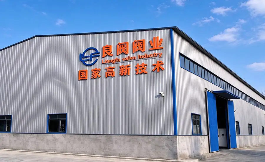
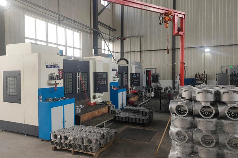
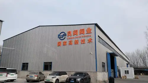
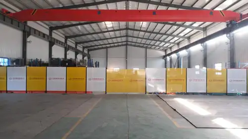
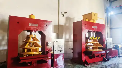
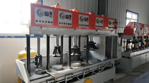
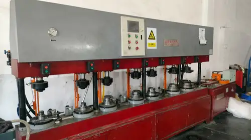
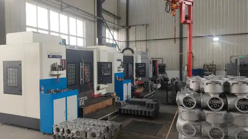
We support product selection, technical documentation, configuration confirmation, and pre-shipment inspection. Our team can help check actuator and valve interface details, control requirements, and optional accessories before production. Inspection records, material documentation, and export documents can be discussed according to the order and destination requirements.


Packing and Delivery
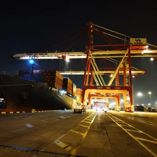
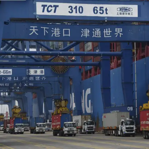
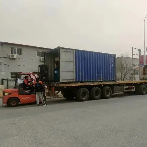
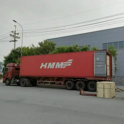
We coordinate packing and shipping according to order quantity, product configuration, and destination requirements. Sea and land transport options can be discussed with our sales team. Before shipment, confirm the actuator model, voltage, control configuration, accessories, and required documentation against the purchase order.
Where It Is Used
Municipal Water and Wastewater
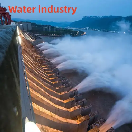
Used on compatible gate, globe, and other multi-turn valves in water-treatment plants, raw-water pipelines, pump stations, sedimentation systems, and wastewater networks. Remote commands and status feedback can help operators manage valves across distributed facilities.
Heating and Power Plants
Suitable for selected valves in heating networks, heat-exchange stations, boiler systems, and power-plant water circuits. Verify temperature exposure, valve torque, pressure conditions, and operating frequency before choosing the actuator configuration.
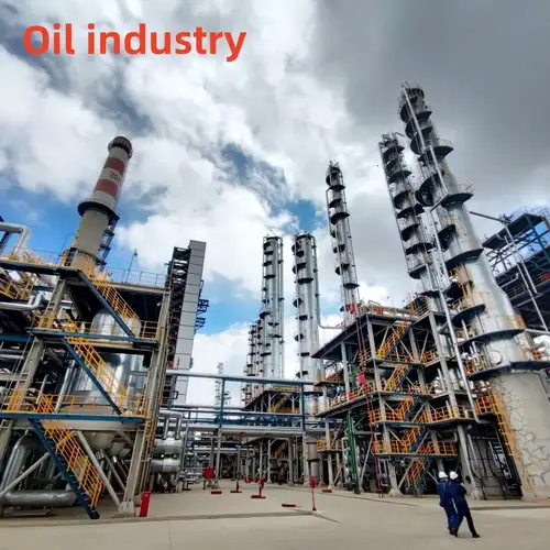
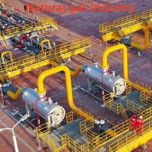
Oil, Gas, and Chemical Processing
For appropriate multi-turn valves in process pipelines and tank-farm systems, the available flameproof version can be considered when its certified marking matches the site classification. Communication options depend on the required control architecture and selected model.
Metallurgy, Mining, and Industrial Utilities
Can be configured for compatible valves in industrial water circulation, dust-handling systems, mine-water networks, and other utility pipelines. Enclosure protection, vibration exposure, maintenance access, and the presence of corrosive media should be assessed for each installation.
Building Services and Other Industries
Potential applications include industrial HVAC, water distribution, paper production, grain processing, and desalination utility systems. The valve material must be suitable for the medium, and the actuator must match the valve's travel, torque, and mounting requirements.
Compatible valve types: Gate valves, globe valves, plunger valves, and compatible knife-gate valves with multi-turn operation. Butterfly and ball valves normally require quarter-turn actuation.



Technical and After-Sales Service
Selection Before Ordering
We can review valve parameters, operating conditions, control signals, communication requirements, and mounting dimensions to help identify a suitable configuration. Drawings, technical data, customization options, and sample arrangements can be discussed based on the project requirements.
Inspection and Shipment
Pre-shipment inspection and available supporting documents can be arranged according to the order. We can also coordinate export packing, shipping arrangements, and the required commercial and technical documentation.
Support After Delivery
We provide technical guidance for installation, commissioning, and maintenance, along with spare-parts support subject to model availability. Our stated service policy is to respond to quality-related feedback within 24 working hours. The standard warranty period is 12 months from shipment, subject to the agreed terms.
Frequently Asked Questions
Does the actuator remember its position after a power failure?
The absolute encoder is designed to retain valve-position information without battery-backed memory. Correct initial calibration and proper installation are still necessary. After power is restored, operators should check the displayed position and system status before returning the valve to automatic operation.
Can I use the same model for both on-off and modulating control?
Not necessarily. On-off and modulating versions use different control configurations. If the application requires 4–20 mA positioning, specify a modulating model at the selection stage and confirm the required feedback signal, dead-zone settings, and operating frequency.
What information should I send for actuator sizing?
Please provide the valve type, nominal size, pressure rating, maximum operating torque, full-stroke rotations, stem and flange dimensions, medium, temperature, required opening or closing time, power supply, control mode, and installation environment. For hazardous locations, include the area classification and required certification.
Is IP67 protection standard?
No. The supplied configuration lists IP55 as standard and IP67 as optional. The required protection level depends on exposure to rain, dust, moisture, and cleaning procedures. Confirm the final enclosure rating and any special exposure requirements before ordering.
Can the flameproof version be installed in any hazardous area?
No. The available Ex d IIB T4 version must only be used where its complete certified marking and permitted installation conditions match the site's hazardous-area classification. Confirm the gas group, temperature class, zone, certificate, cable-entry components, and applicable local regulations with the project engineer.
Is it suitable for continuous, high-frequency valve movement?
The listed duty rating is S4 intermittent duty, so suitability depends on operating frequency, load, start duration, and rest periods. For frequent small-stroke regulation or prolonged modulation, provide the expected movement cycle and consult us to verify that the selected model meets the duty requirements.
Which communication protocols are available?
Modbus RTU, Profibus-DP, and HART are optional, subject to the selected model. Please specify your PLC or DCS interface and the required command, feedback, and diagnostic data so compatibility can be checked before purchase.
Can Liangfa help with valve matching and commissioning?
Yes. We can review the valve's torque, travel, mounting interface, supply voltage, and control requirements before order confirmation. After delivery, we can provide technical guidance for installation and commissioning based on the supplied model documentation.
Contact Liangfa with your valve specifications and operating requirements. We can help review the appropriate actuator configuration, mounting interface, control mode, and protection options for your application.
Related Category
Send Inquiry
Contact Info
-
Address
No. 2 Taikang Road, Xiditou Town, Beichen District, Tianjin City, China
-
Tel
-
Email
If you have any inquiry about a quotation or cooperation, please feel free to email or use the following inquiry form. Our sales representative will contact you within 24 hours.
News Recommendations