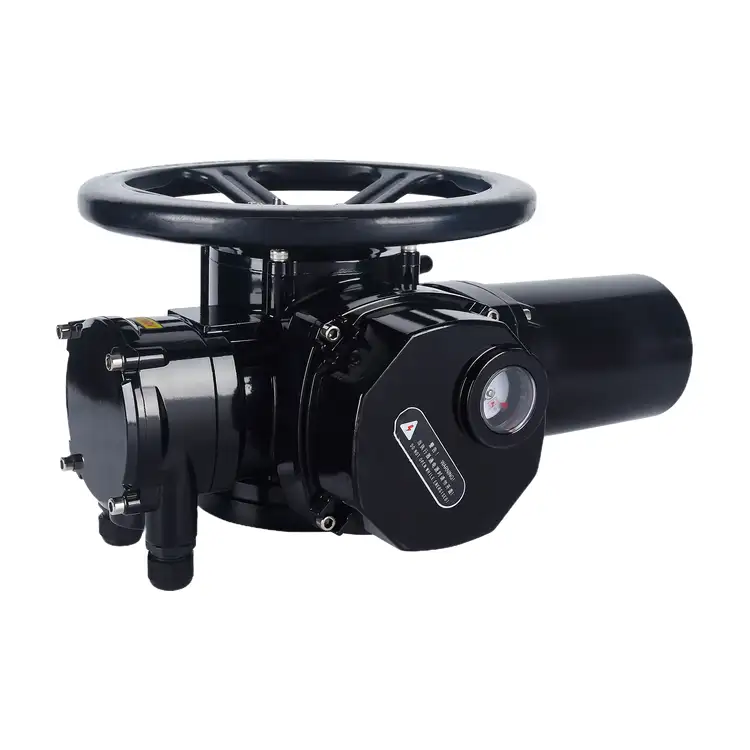
Split-type Multi-turn Electric Actuator
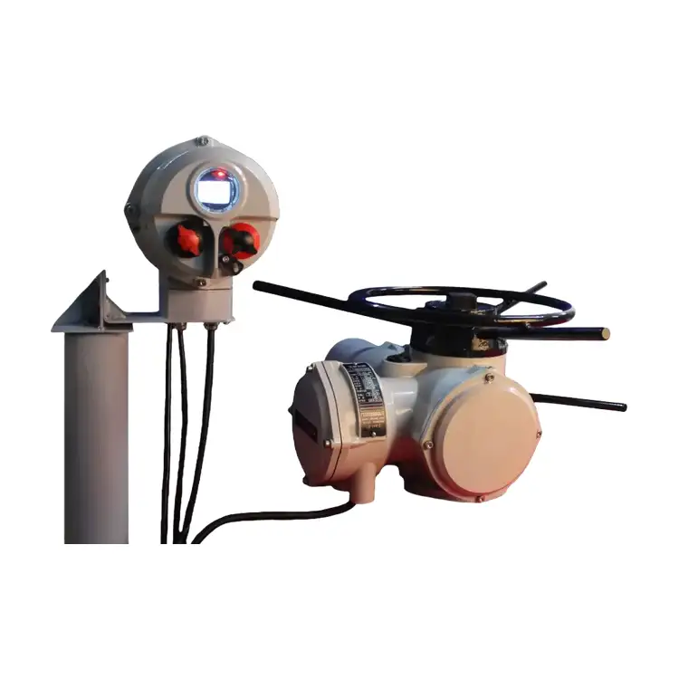
Liangfa provides split-type multi-turn electric actuators for automated control of gate valves, globe valves, and other compatible industrial valves. Featuring a separate mechanical drive unit and remote control box, our actuators support on-off and modulating control, with optional 4–20 mA signals and fieldbus communication.
Liangfa supplies split-type multi-turn electric actuators for industrial valve automation where the mechanical drive and electrical control unit need to be installed separately. Designed for multi-turn valves such as gate valves and globe valves, our actuators support on-off operation and modulating control for demanding industrial applications.
The main feature of this design is the separation of the valve-mounted actuator body from the remote control box. This arrangement allows the drive unit to be installed near the valve while the control box is positioned in a more accessible location away from excessive heat, vibration, and dust. With ISO 5210 mounting compatibility, multiple control options, and a cable transmission distance of up to 200 m under suitable conditions, Liangfa offers a practical solution for industrial valve control systems.
How the Separate Design Works
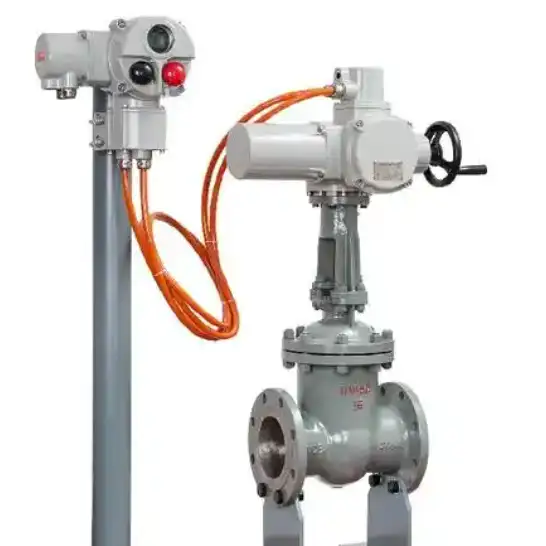
A split-type multi-turn electric actuator consists of two main modules: a mechanical actuator body installed on the valve and a separate electrical control box. A dedicated shielded cable connects the two units to transmit power and control signals. This layout is particularly useful when the valve is installed on an elevated pipeline, near hot equipment, or in an area where direct access to the actuator controls is inconvenient.
Mechanical Drive at the Valve
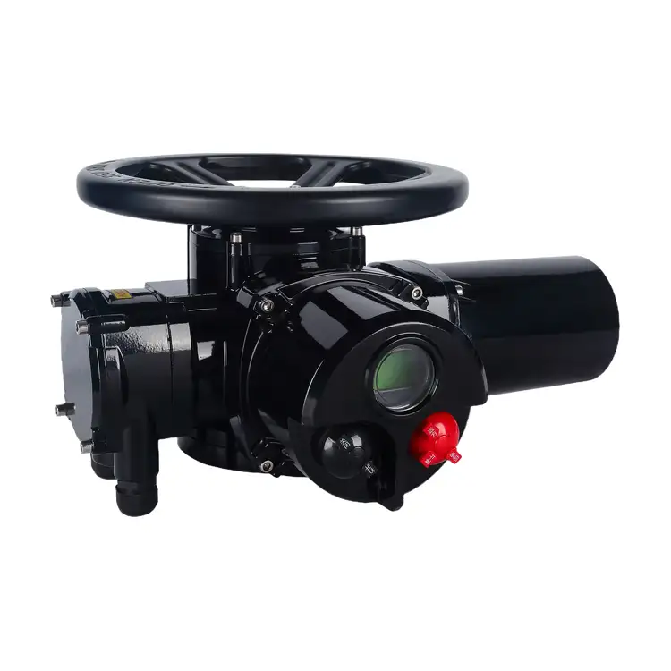
The valve-side unit contains the drive motor, worm-and-wormwheel reduction mechanism, output connection, manual handwheel, and position and torque monitoring components. It delivers the multi-turn output required to operate compatible gate valves, globe valves, and other quarter-turn-incompatible valve configurations designed for multi-turn actuation. Travel-limit and over-torque protection help prevent damage caused by incorrect travel settings or excessive resistance during operation.
Control Box in an Accessible Location
The remote control box provides local operating buttons, an LCD display, parameter settings, and electrical signal interfaces, depending on the selected configuration. Operators can check valve position, adjust settings, and carry out commissioning without needing to access the valve-mounted unit directly. For systems connected to a PLC or DCS, optional communication interfaces can support centralized monitoring and control.
Control Options for Different Processes
Choosing the correct control mode depends on whether the valve is used for simple isolation or continuous process regulation. We help customers confirm the control method, signal type, feedback requirements, and communication protocol before production.
On-Off Operation
The on-off version is designed for two-position control, typically moving a valve to its fully open or fully closed position. Depending on the configuration, it can support local open/close/stop operation, remote switching commands, valve-position feedback, and fault-alarm outputs. It is suitable for isolation duties where continuous intermediate-position regulation is not required.
Modulating Control
The modulating version supports a 4–20 mA command signal and can provide 4–20 mA valve-position feedback. A built-in PID function is available for supported configurations. This option is intended for applications requiring adjustable valve positioning as part of a process-control loop. The required input, output, and control logic should be confirmed against the customer's PLC or DCS specifications.
Communication and Power Supply
Standard power options include AC380V three-phase and AC220V single-phase, subject to the selected model. Modbus-RTU, HART, and Profibus are available as optional communication choices where supported. Before ordering, confirm the power supply, protocol version, communication wiring, and required monitoring data to avoid integration problems during commissioning.
Technical Specifications
| Item | Specification |
| Product Name | Split-type Multi-turn Electric Actuator |
| Mounting Standard | ISO 5210 mounting; JB/T 8216 |
| Structure | Separate mechanical actuator body and remote control box |
| Actuator Body Protection | IP67 |
| Control Box Protection | IP65 or IP67, depending on configuration |
| Power Supply | AC380V three-phase or AC220V single-phase |
| Control Modes | On-off or modulating control |
| Modulating Signal | 4–20 mA, with built-in PID on supported versions |
| Optional Communication | Modbus-RTU, HART, Profibus, subject to configuration |
| Ambient Temperature | -30°C to +70°C |
| Control Cable Distance | Up to 200 m under suitable cable and installation conditions |
| Hazardous-Area Option | Explosion-proof version available; confirm certification and installation requirements |
Match the Actuator to the Valve
Correct selection begins with the valve manufacturer's technical data rather than nominal pipe diameter alone. A suitable actuator must deliver sufficient torque, provide the required number of turns, fit the valve mounting interface, and meet the process control requirements.
Check Torque and Operating Time
We recommend using the valve manufacturer's specified operating torque as the primary selection reference. The actuator's rated output torque should provide an appropriate safety margin for the actual operating conditions. A preliminary sizing factor of 1.2–1.5 may be considered where appropriate, but the final value should be confirmed against valve data, service conditions, and the actuator manufacturer's recommendations.
Output speed affects how long the valve takes to travel between its end positions. The approximate operating time can be estimated from the required number of valve turns and the actuator's output speed. The final choice should consider process response, valve operating limits, and the risk of pipeline pressure surges caused by excessively rapid movement.
Confirm the Mounting Interface
The valve flange, stem diameter, stem thread, keyway, and required number of turns must be compatible with the actuator. ISO 5210 mounting interfaces are available in different sizes, so the standard alone does not guarantee a direct fit. We recommend checking the valve drawing and actuator dimensional drawing before confirming the order.
Choose the Right Control Configuration
Before selecting a control box, confirm whether the application needs on-off or modulating operation, local controls, remote commands, position feedback, fault contacts, or fieldbus communication. The cable distance between the actuator body and control box should also be specified in advance so the correct shielded cable and cable-entry accessories can be selected.
Designed for Challenging Installation Sites
A split configuration is most useful when the valve and its controls face different installation constraints. Separating the two modules gives engineers more flexibility when arranging the equipment, although each component must still be installed within its specified environmental limits.
Hot Pipelines and Boiler Areas
For steam lines, boiler equipment, and heating systems, the control box can be located away from direct thermal radiation. The actuator body, motor, and connecting cable must still be suitable for the temperature around the valve. Heat shields and temperature-resistant cables may be necessary where the site conditions require them.
Elevated Valves and Pipe Racks
When valves are installed on high pipe racks or other difficult-to-reach locations, the mechanical unit can remain at the valve while the control box is mounted at a more accessible level. This arrangement can simplify routine operation and commissioning and reduce the need for repeated access to elevated equipment.
Dusty, Humid, and Outdoor Locations
The IP67 actuator body and the selected IP65/IP67 control box help protect equipment against dust and water exposure within their specified ratings. Correct cable glands, intact seals, suitable mounting orientation, and regular inspection remain essential. For corrosive or coastal environments, confirm the coating and material options required for the site.
Hazardous Areas
An explosion-proof version may be available for applications involving flammable gases or vapors. The suitability of the actuator depends on the hazardous-area classification, required protection concept, applicable certification, and the installation of approved cable glands and conduits. The control box must be located and protected according to the approved system design; a split structure alone does not make an installation explosion-proof.
Installation and Commissioning Checks
Proper installation helps the actuator operate smoothly and protects both the actuator and the valve from avoidable damage. We recommend that qualified personnel follow the product manual, site electrical procedures, and the valve manufacturer's instructions.
Before Mounting
Check the model, rated torque, output speed, power supply, control mode, protection rating, and mounting dimensions against the purchase specification. Inspect the valve stem for corrosion, bending, or sticking. Confirm that the valve can be operated manually and that the mounting flange and output connection are compatible.
During Wiring
Isolate the power supply before electrical work. Use the specified shielded cable between the actuator body and control box, keep signal wiring appropriately separated from power wiring, and establish grounding in accordance with the wiring diagram. For three-phase models, verify the phase sequence before powered operation. Hazardous-area installations must use the required certified cable-entry components.
During Commissioning
Confirm that the display and control functions work correctly before carrying out a full-stroke test. Set the open and closed travel limits according to the valve's actual travel, then verify torque protection and position feedback. Test local and remote commands, analog signals, and communication functions where fitted. Do not use the actuator's over-torque protection as a substitute for correct travel-limit settings.
Maintenance That Helps Reduce Downtime
Routine inspection can identify problems before they interrupt plant operation. Maintenance frequency should reflect operating cycles, ambient conditions, vibration, and the manufacturer's instructions.
- Inspect the actuator-to-valve mounting bolts, handwheel, housing, and cable glands for looseness, damage, or corrosion.
- Check the control-box display, position feedback, alarm indications, and remote commands.
- Look for cable aging, damaged seals, water ingress, and signs of overheating.
- During planned shutdowns, verify full-stroke operation and investigate abnormal noise, sticking, or repeated torque alarms.
- Have qualified personnel inspect lubrication, terminals, grounding, and position calibration according to the service manual.
If the actuator fails to move, the cause may be a power-supply issue, damaged cable, active torque protection, incorrect wiring, or a mechanically jammed valve. Repeated alarms should be investigated rather than bypassed by raising protection settings without checking the valve and drive system.
Manufacturing and Delivery Support
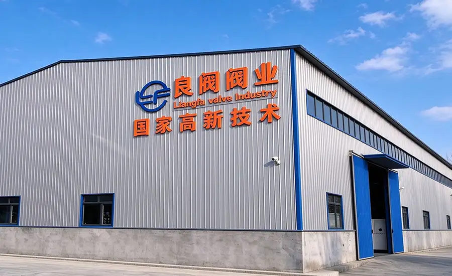
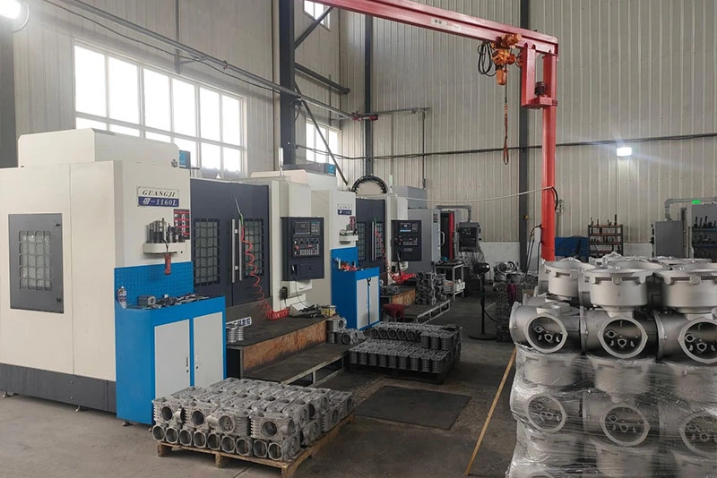
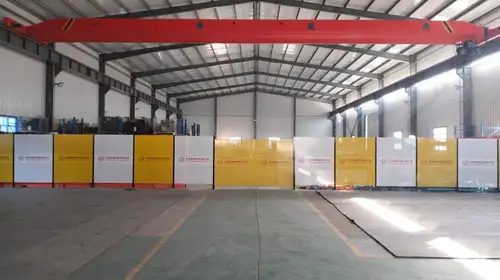
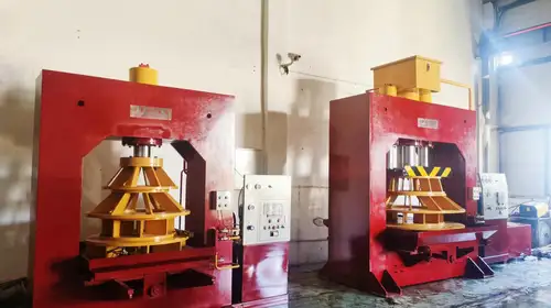
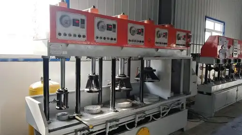
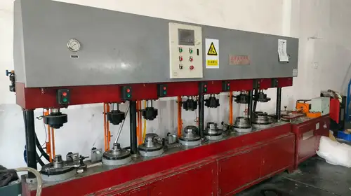
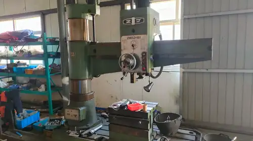
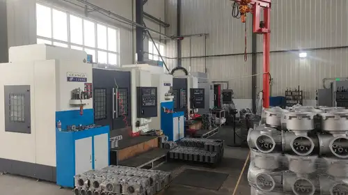
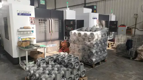
At Liangfa, we support customers from technical selection through delivery and after-sales service. As a High-Tech Enterprise, we can assist with confirming valve compatibility, control requirements, and installation conditions before the order is finalized. The specific inspection records and technical documents supplied with an order depend on the agreed product configuration and purchase requirements.
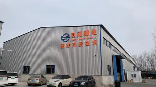
Factory Tour
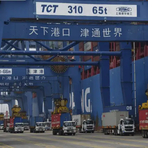
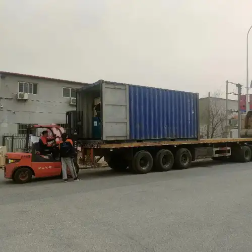
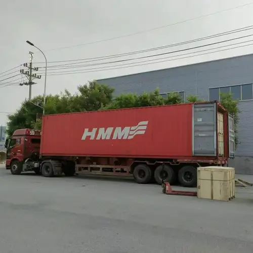
Packing and Shipping
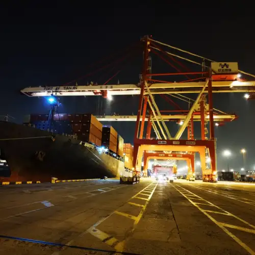
We arrange export packing and shipping according to the order quantity, destination, and agreed delivery terms. Sea freight and land transport can be coordinated for suitable destinations. Before shipment, customers should confirm the actuator model, accessories, cable requirements, and any required documentation.
Where These Actuators Are Used
Liangfa actuators can be considered for compatible multi-turn valves in a range of industrial systems. Final suitability depends on valve torque, process conditions, environmental protection, and the required control configuration.
Power Generation and District Heating
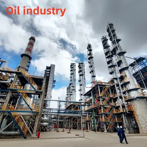
Applications include boiler-related valves, steam pipeline isolation, and heating-network systems where valve operation may be affected by thermal radiation or limited access.
Petrochemical and Process Plants
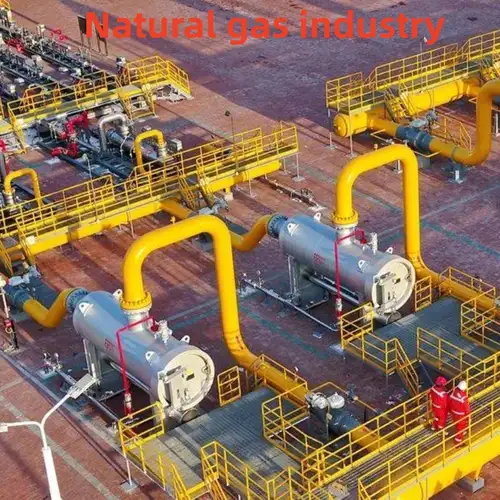
Gate and globe valves in process pipelines, tank-farm systems, and wastewater lines may require remote operation, position feedback, or a properly specified hazardous-area solution.
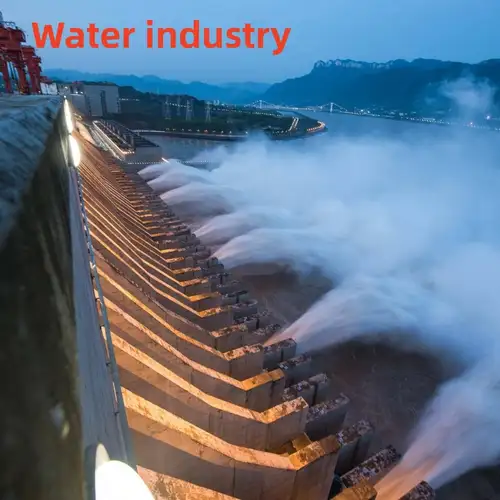
Water and Wastewater Treatment
Pump stations, filter systems, sludge lines, and outdoor water-treatment facilities can use multi-turn actuators for automated valve operation, subject to the valve and environmental requirements.
Metallurgy and Heavy Industry
In dusty or vibration-prone facilities, the separate control box can be positioned away from the most severe local conditions when the installation layout permits.
Coastal Facilities and High-Level Pipelines
Desalination plants, coastal installations, and elevated pipe racks may benefit from flexible control-box placement. Material protection, cable routing, and maintenance access should be assessed for each site.



Technical and After-Sales Assistance
We provide pre-sales model selection guidance, technical parameter confirmation, and quotation support. Customized configurations may be discussed for mounting interfaces, control signals, communication options, and environmental requirements, subject to product availability and technical review.
Before delivery, the agreed inspection scope and documentation can be confirmed with the order. We can also provide remote guidance for installation, commissioning, and routine maintenance. Spare-parts availability, warranty conditions, and response arrangements should be specified in the quotation or sales contract.
Frequently Asked Questions
Can the control box be installed far from the actuator body?
The stated cable transmission distance is up to 200 m under suitable conditions. The actual distance depends on cable type, signal requirements, electrical interference, and installation layout. We recommend confirming the cable specification and routing before ordering.
Is a split actuator suitable for every multi-turn valve?
No. Compatibility depends on valve operating torque, required turns, mounting flange, stem dimensions, and control requirements. Please provide the valve datasheet or dimensional drawing so we can help verify the match.
What information is needed for a quotation?
Please provide the valve type, rated operating torque, number of turns, mounting dimensions, power supply, control mode, required feedback or communication protocol, ambient temperature, protection rating, and any hazardous-area requirements. These details help us recommend an appropriate configuration.
Does IP67 mean the actuator can remain underwater indefinitely?
No. IP67 is a defined ingress-protection rating and should not be interpreted as permission for continuous underwater operation in every installation. Confirm the product's certified rating, immersion conditions, cable-entry protection, and installation requirements before use.
Can the actuator continue to operate during a power failure?
The manual handwheel allows manual operation where the supplied configuration supports it. It does not provide automatic electric operation without power. Operators should follow the product manual and site safety procedures when switching to manual operation.
What should be checked if the actuator repeatedly trips on torque protection?
Check for valve-stem sticking, mechanical misalignment, incorrect travel settings, and operating torque beyond the selected actuator's capacity. Do not simply increase the torque setting without identifying the cause, because doing so may expose the valve stem and drive mechanism to damage.
Related Category
Send Inquiry
Contact Info
-
Address
No. 2 Taikang Road, Xiditou Town, Beichen District, Tianjin City, China
-
Tel
-
Email
If you have any inquiry about a quotation or cooperation, please feel free to email or use the following inquiry form. Our sales representative will contact you within 24 hours.
News Recommendations