Electric Grooved Butterfly Valve
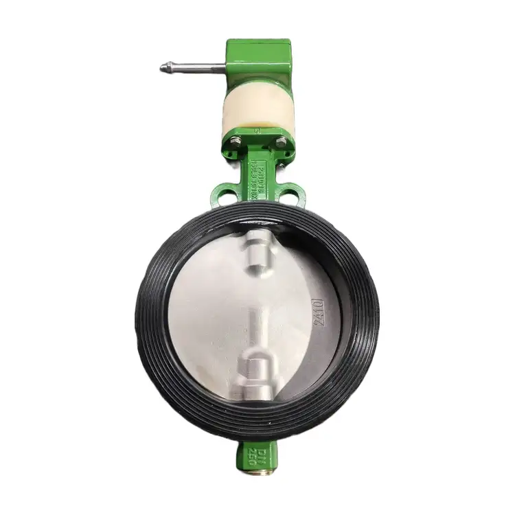
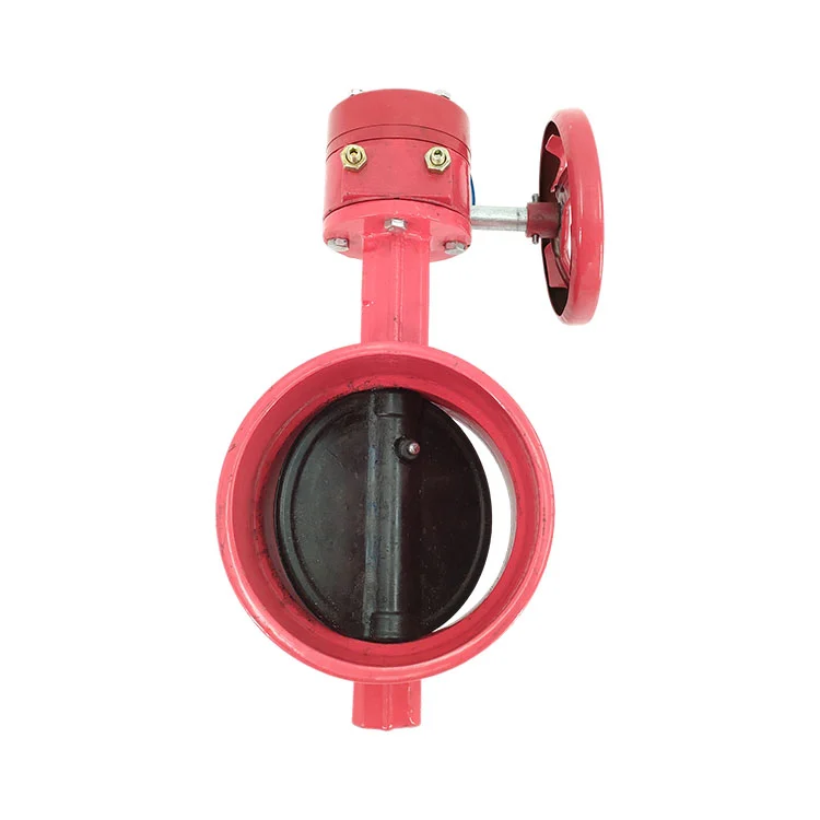
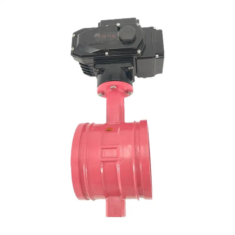
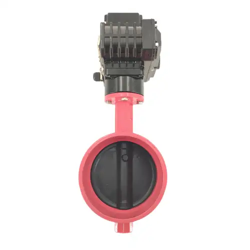
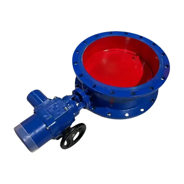
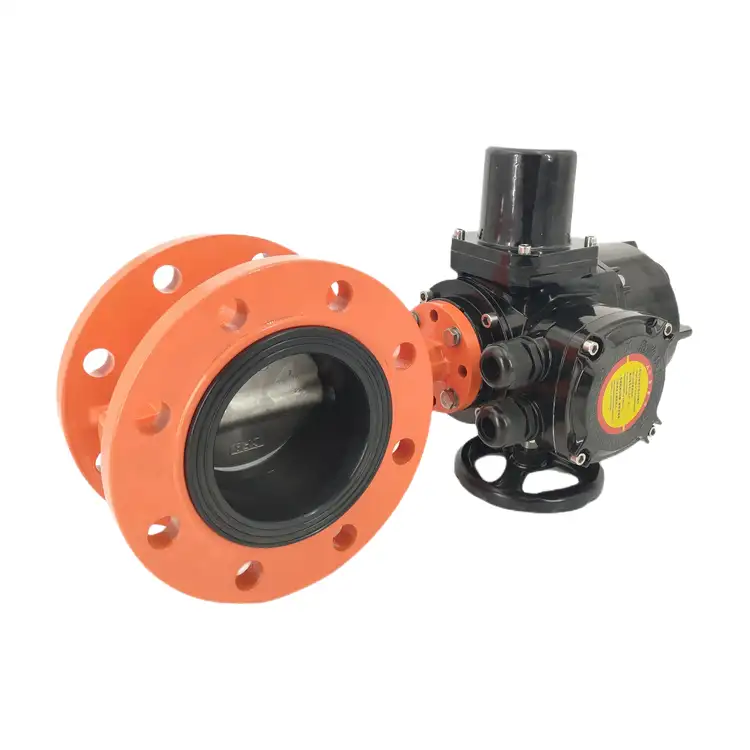
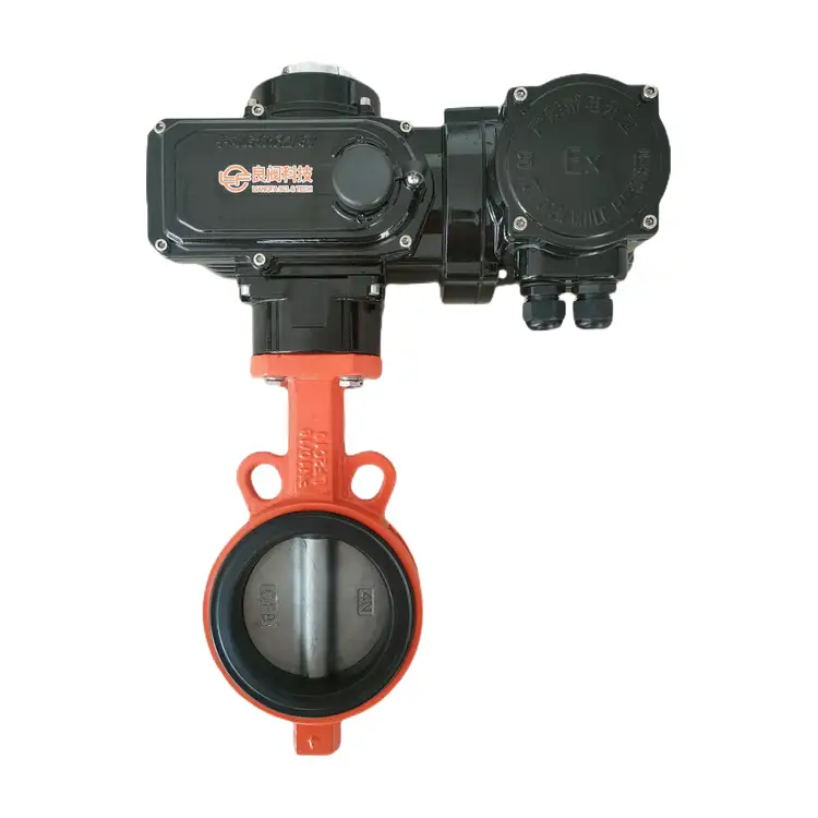
The Electric Grooved Butterfly Valve is designed for automated flow control in fire protection, HVAC, building water supply, and industrial water circulation systems. Its grooved connection allows convenient installation and maintenance, while the electric actuator supports remote on-off operation or modulating control, depending on the selected configuration. Liangfa offers multiple body, disc, stem, and seat materials to suit different media and operating conditions.
The Electric Grooved Butterfly Valve combines an electric actuator with a soft-seated butterfly valve for automated flow control in fire protection, HVAC, building water supply, and industrial circulation systems. Its grooved connection supports convenient installation and disassembly, making it suitable for pipeline projects where maintenance access and installation efficiency matter. At Liangfa, we offer different body, disc, stem, and seat materials, along with on-off and modulating actuator options, to help customers match valve performance to operating pressure, media, and control requirements.
Product Specifications
| Model | D981X-10/16Q |
| Nominal Diameter | DN40–DN1200 (confirm available sizes for the selected model) |
| Connection | Grooved connection; verify the connection standard before ordering |
| Working Pressure | PN10 / PN16; other listed pressure standards require confirmation |
| Temperature Range | -10°C to 100°C, subject to the selected seat material and configuration |
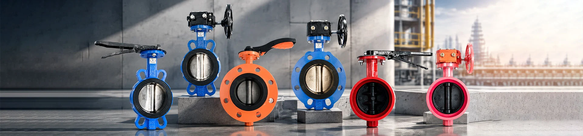
| Body Material | Cast Iron, Ductile Iron, WCB, SS304, SS316 |
| Disc Material | Ductile Iron, SS304, SS316, SS2507, SS1.4529 |
| Stem Material | 410SS, SS304, SS316, SS2507, SS1.4529 |
| Seat Material | EPDM, NBR, PTFE, FKM (Viton) |
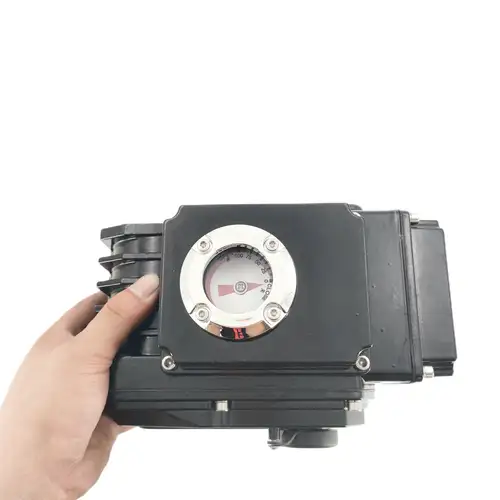
| Actuator | On-off or modulating type |
| Actuator Protection | IP65 as specified for the offered actuator |
| Coating | Fusion-bonded epoxy coating to ANSI/AWWA C550, where applicable |
How the Grooved Connection Helps
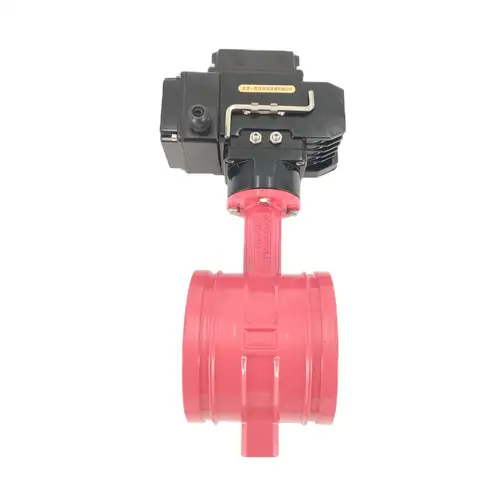
The grooved connection is designed to simplify pipeline assembly and future maintenance. Instead of welding the valve into the line, installers use compatible grooved pipe ends, gaskets, and couplings. This can reduce installation work and make it easier to remove the valve when inspection or replacement is required.
The compact body is useful in pump rooms, mechanical rooms, and building service areas where several pipelines run close together. Before installation, the pipe groove dimensions, coupling type, gasket specification, and valve connection must be checked for compatibility.
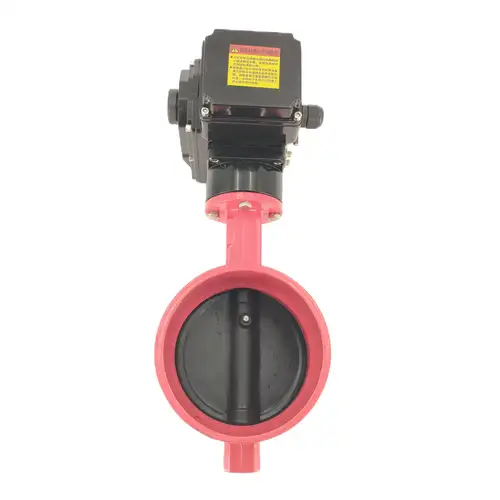
The Electric Grooved Butterfly Valve uses a rotating disc to control flow. When fully open, the disc allows flow through the pipeline; when closed, the soft seat presses against the disc to provide shutoff. Actual leakage performance depends on the seat, media, pressure, installation, and test requirements.
Choose Materials for the Medium
We offer several material combinations because the valve body, disc, stem, and seat have different functions. The correct combination depends on the liquid, temperature, pressure, and required service life.
| Component | Available Options | Selection Notes |
|---|---|---|
| Body | Cast Iron, Ductile Iron, WCB, SS304, SS316 | Ductile iron is commonly considered for building water systems; other materials require compatibility and pressure checks. |
| Disc | Ductile Iron, SS304, SS316, SS2507, SS1.4529 | Stainless steel options may be appropriate where corrosion resistance is needed. |
| Stem | 410SS, SS304, SS316, SS2507, SS1.4529 | Select according to the medium and corrosion conditions. |
| Seat Liner | EPDM, NBR, PTFE, FKM (Viton) | Confirm chemical compatibility and the permitted temperature range. |
| Fasteners | Galvanized Carbon Steel, SS304, SS316 | Choose according to the installation environment. |
EPDM for Water Systems
EPDM is a common option for clean water, fire protection water, and HVAC circulating water when the operating conditions fall within its rated limits. It is generally not suitable for oil-bearing media or certain organic solvents.
NBR for Oil-Contaminated Water
NBR may be considered for selected oil-bearing cooling water and compatible wastewater applications. Confirm the oil type, temperature, and chemical composition before specifying it.
PTFE for Selected Corrosive Media
PTFE may be suitable for certain mildly corrosive fluids. Its use must be checked against the actual chemical concentration, operating temperature, pressure, and cycling requirements.
Important: Do not assume one seat material is suitable for every application. For fire protection projects, confirm the required valve and seal specifications against the applicable project standards and approval requirements.
Configure the Electric Actuator
The actuator determines how the valve responds to local commands, remote signals, and automated control systems. We can help match the actuator type to the control method required by the project.
On-Off Control
An on-off actuator drives the valve toward the fully open or fully closed position. Depending on the actuator configuration, position feedback can be provided to a control panel or building management system. This option is suitable when the system requires switching rather than continuous flow adjustment.
Modulating Control
A modulating actuator can accept a 4–20 mA or 0–10 V command when the selected model supports that signal. It adjusts the valve position according to the control input and can be used in suitable HVAC or water distribution systems.
Flow control performance depends on valve sizing, actuator capability, system pressure, and the control strategy. A modulating actuator alone does not guarantee precise flow measurement or regulation.
Power and Optional Accessories
Common actuator supply options described for this product range include AC220 V, AC380 V, and DC24 V. The correct supply depends on the selected actuator and project control panel, so please confirm it before placing an order.
- Valve position feedback
- Emergency manual operation
- Outdoor rain protection
- Moisture-proof heating for damp installations
- Explosion-proof actuator versions for suitable hazardous-area applications
- Power-loss return functions, if supported by the selected actuator
Power-loss opening or closing behavior must be specified explicitly. It should not be assumed that every actuator automatically moves to a safe position when power is interrupted.
Match the Valve to the Project
The following configurations are starting points for technical discussion, not substitutes for checking the actual operating conditions.
| Application | Initial Selection Considerations |
|---|---|
| Fire hydrant and sprinkler water systems | Confirm the required pressure rating, approved valve configuration, EPDM compatibility, actuator signal, and fire-system acceptance requirements. |
| HVAC chilled or cooling water | EPDM may be considered for compatible water service; choose on-off or modulating control according to the system design. |
| Building water supply | Check water-contact material requirements, disc material, pressure rating, and applicable local regulations. |
| Oil-contaminated cooling water | Consider NBR only after confirming compatibility with the oil and operating temperature. |
| General sewage and rainwater | Assess solids content, risk of seat damage, and whether upstream filtration or another valve design is needed. |
| Mildly corrosive circulating water | Review the fluid composition and evaluate PTFE or corrosion-resistant metal components as appropriate. |
| Outdoor or damp pump rooms | Confirm actuator protection, cable entry sealing, condensation control, and any required weather cover. |
When Another Valve Design May Be Needed
This soft-seated valve should not be selected automatically for steam, high-temperature service, strongly corrosive chemicals, organic solvents, or abrasive slurry. Such duties may exceed the limits of the body, seat, or actuator. Please provide the medium composition and operating conditions so we can assess whether another construction is more appropriate.
Installation Checks Before Commissioning
Correct installation helps prevent disc obstruction, joint leakage, and actuator overload.
- Check the order details. Confirm model, nominal diameter, pressure rating, seat material, actuator voltage, and control type against the nameplate and purchase documents.
- Inspect the pipeline. Remove debris, welding residue, and foreign objects that could damage the seat or obstruct the disc.
- Verify the connection. Confirm the pipe groove dimensions, coupling, gasket, and installation procedure match the selected valve. Do not assume every grooved valve uses the same coupling standard.
- Support the pipework. Arrange independent pipe supports so the valve does not carry excessive pipeline weight or misalignment stress.
- Check disc clearance. Make sure the disc can rotate through its required travel without contacting the adjacent pipe or other components.
- Wire the actuator correctly. Follow the supplied wiring diagram and verify the power supply before energizing. Keep control and feedback wiring arranged according to the actuator instructions.
- Test the operation. Run the valve through its travel and check the open/closed indication. For modulating versions, verify the control signal and position response.
- Inspect the joints. After installation and pressure testing, check the connections for leakage in accordance with the project procedure.
For fire protection systems, installation, testing, and commissioning should follow the approved project design and applicable local fire codes.
Maintenance for Reliable Operation
The maintenance interval should be based on operating frequency, water quality, environment, and the manufacturer's instructions.
- Routine checks: Inspect the coupling, visible joints, actuator housing, cable entries, and position indicators for damage or abnormal conditions.
- Operational checks: Where permitted by the system operating procedure, cycle the valve and confirm smooth travel.
- Seat inspection: Investigate leakage, excessive operating torque, or incomplete closure. Debris, seat wear, incorrect travel limits, and pipeline stress can all contribute.
- Actuator inspection: Check terminals, limit switches, feedback signals, and moisture ingress according to the actuator manual.
- After long shutdowns: Inspect the valve before returning it to service; do not force the actuator if the disc appears stuck.
Lubrication, disassembly, and seal replacement should follow the specific maintenance instructions for the supplied model. Do not apply lubricant to the seat or wetted components unless the manufacturer confirms it is suitable.
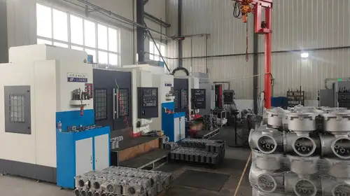
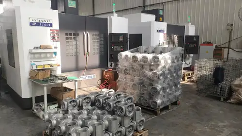
Factory and Quality Support
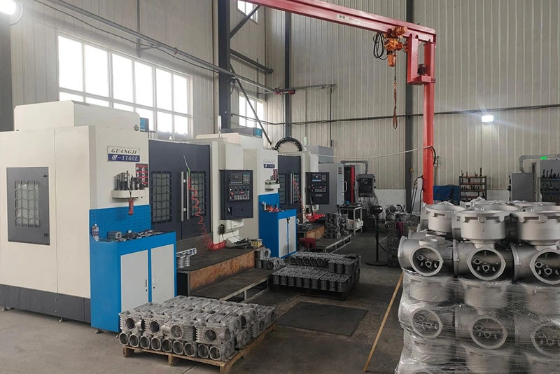
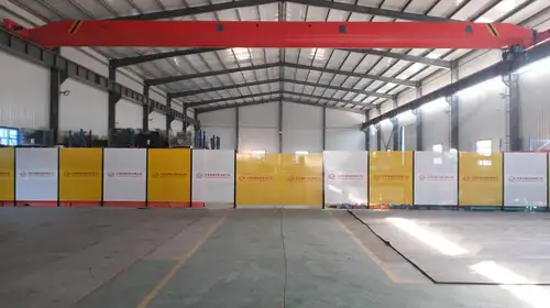
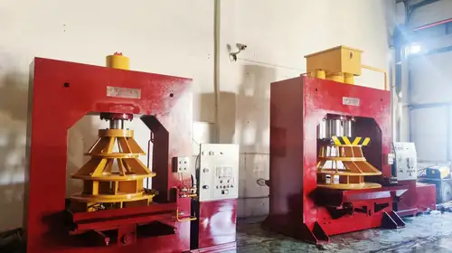
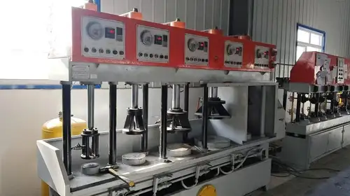
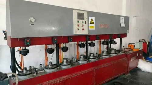
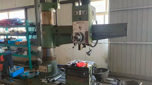
At Liangfa, we support valve selection by reviewing the medium, pressure, nominal diameter, temperature, connection requirements, and actuator control signals. We can provide available product drawings, technical data, material recommendations, and quotation support for the selected configuration.
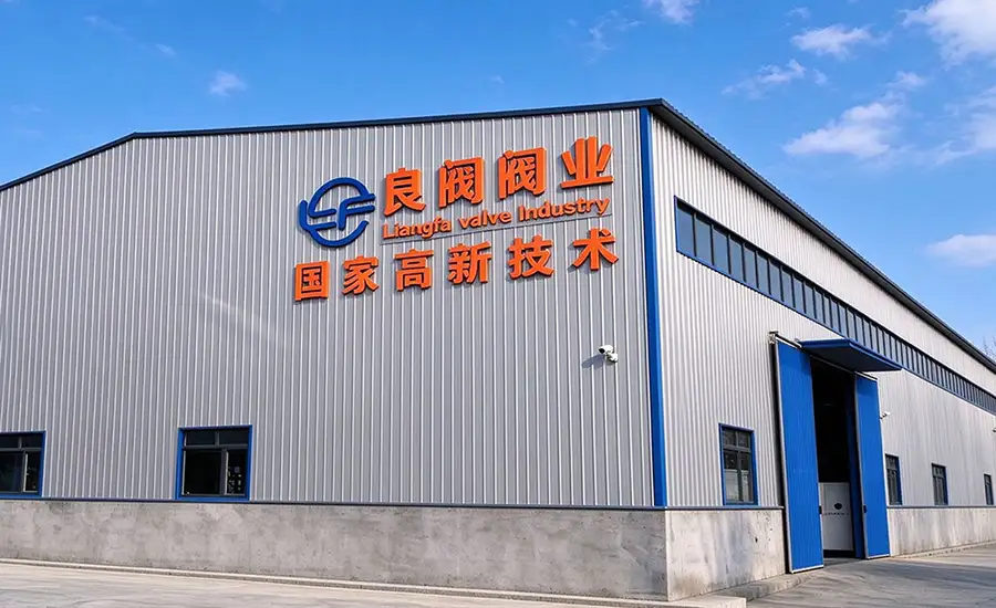
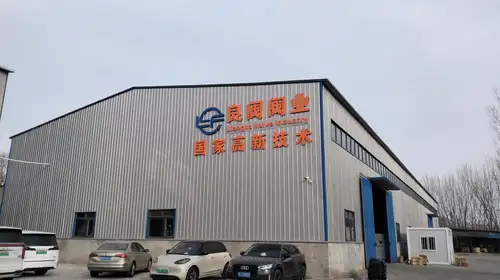
Liangfa holds a High-Tech Enterprise Certificate. Product inspection records and material documents can be discussed according to the order requirements and the documentation available for the supplied product.
Packing and Shipping
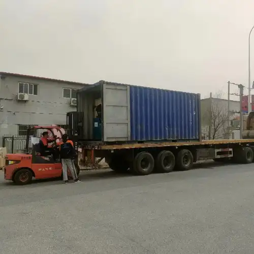
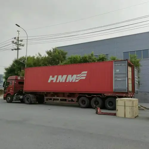
We arrange export packing and shipping according to order quantity, destination, and transport requirements. Before dispatch, buyers can confirm the packing method, shipping marks, and required export documents with our team. Available documents depend on the product and order specifications.


Where It Is Used
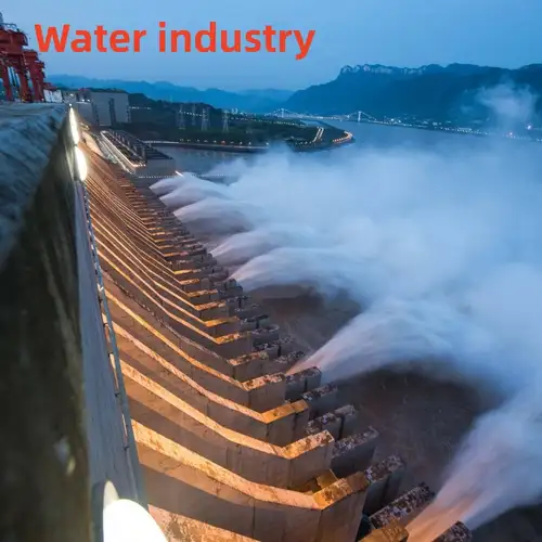
Fire protection water systems: Fire hydrant lines, sprinkler piping, and pump-room installations, subject to project approval and specified valve requirements.
HVAC: Chilled water, cooling water, and suitable circulation loops.
Building services: Water supply and drainage systems in commercial buildings, residential projects, and utility rooms.
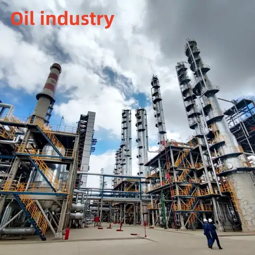
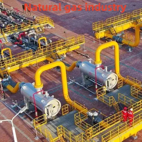
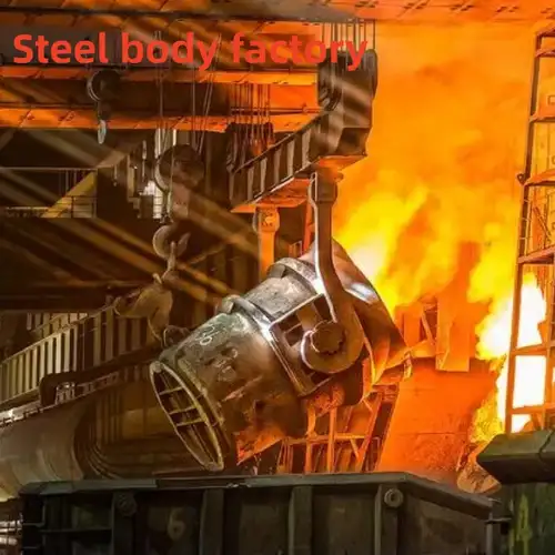
Industrial circulation: Selected cooling-water systems where the body and seat materials match the medium.
Municipal and utility pipelines: Compatible water distribution and service lines where grooved connections are specified.


Frequently Asked Questions
What information should I provide to get a quotation?
Please send the nominal diameter, working pressure, medium, operating temperature, connection standard, required seat material, actuator voltage, and control type. For automated systems, also specify the required feedback signals and whether modulating control is needed.
Can the Electric Grooved Butterfly Valve be controlled by a PLC or building management system?
It may be integrated when the selected actuator supports the required input and output signals. On-off control and modulating control have different wiring and signal requirements, so we need to confirm the actuator model and control scheme.
Is the valve suitable for fire protection projects?
It may be suitable when the valve configuration meets the project's pressure, material, connection, actuator, and approval requirements. Fire protection acceptance depends on the applicable standards and project specifications; confirm these before ordering.
What should I do if the valve does not close completely?
First check for debris between the disc and seat, then inspect the seat condition, actuator travel limits, and coupling alignment. Isolate the pipeline safely before inspection, and follow the manufacturer's maintenance instructions.
Can I use the same seat material for water and oil-bearing media?
Not necessarily. EPDM is commonly considered for compatible water service, while NBR may be appropriate for selected oil-bearing media. The final choice depends on the exact fluid composition, temperature, and operating conditions.
What is the warranty period?
The supplied product information specifies a warranty period of 12 months from shipment. Please confirm the applicable warranty terms, exclusions, and claim procedure in the quotation or sales contract.
Send Inquiry
Contact Info
-
Address
No. 2 Taikang Road, Xiditou Town, Beichen District, Tianjin City, China
-
Tel
-
Email
If you have any inquiry about a quotation or cooperation, please feel free to email or use the following inquiry form. Our sales representative will contact you within 24 hours.
News Recommendations