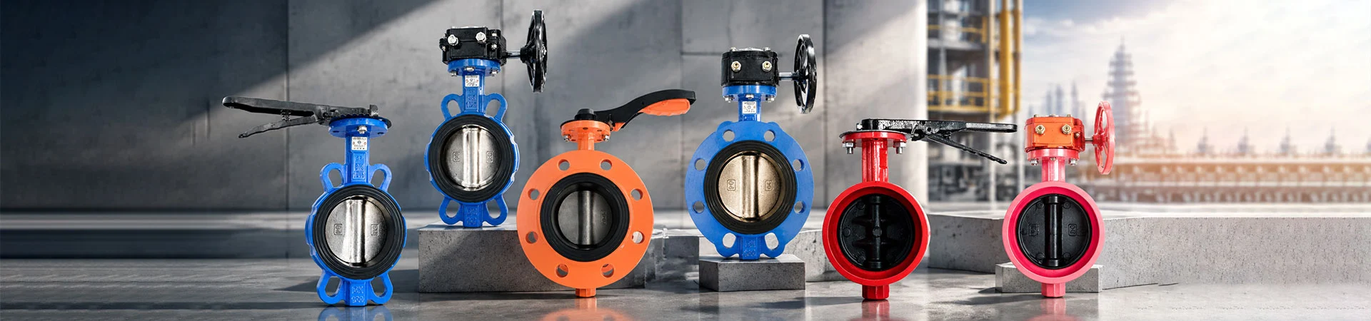
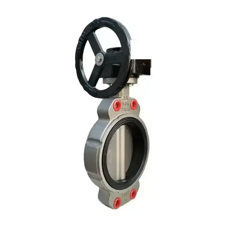
Semi-Lug Butterfly Valve
Liangfa supplies semi-lug butterfly valves for piping systems where installation space is limited and maintenance access is important. With threaded lugs on one side and a wafer-style connection on the other, this design is especially useful at pump outlets and equipment nozzles. We offer different body, disc, stem and seat materials, together with manual, gear-operated, pneumatic and electric actuation options, helping customers configure valves for water treatment, HVAC, marine and general industrial applications.
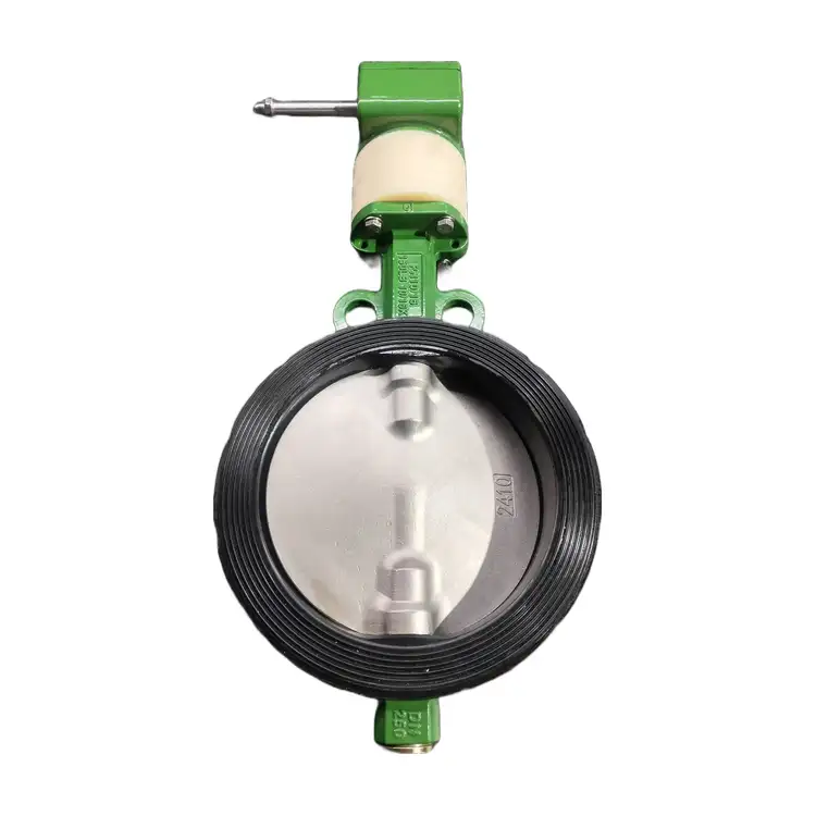
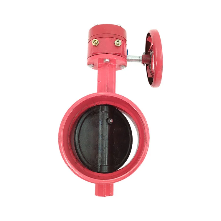
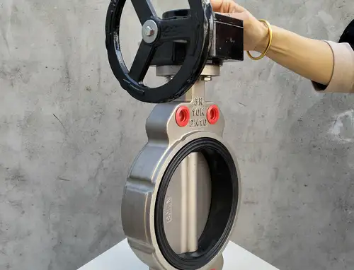
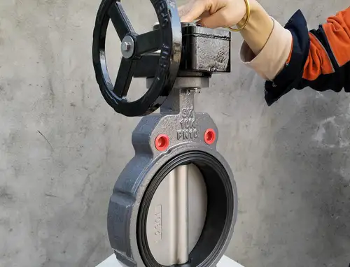
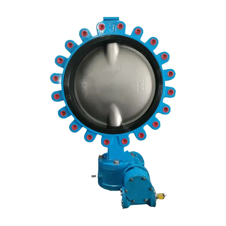
Our semi-lug butterfly valve, model LTD71X-10/16T, uses a concentric disc and soft-seat construction. One side of the body has threaded lugs for direct fastening to an equipment flange, while the opposite side is clamped between pipeline flanges. This arrangement combines compact installation with convenient removal from the pipeline side during maintenance.
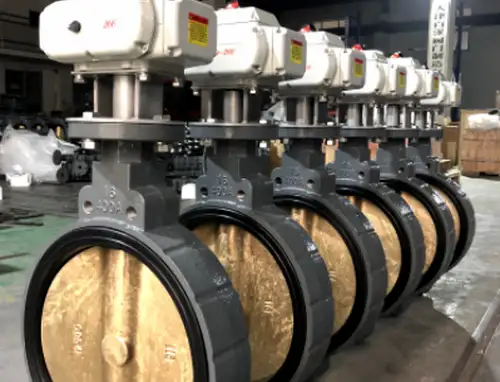
The valve is designed for on-off service and suitable flow-control applications when operating conditions and actuator selection permit. EPDM, NBR, PTFE and FKM seat options are available to match different media. A top mounting platform following the ISO 5211 interface supports compatible manual and automated actuation arrangements.
Important: Only the threaded-lug side may be used for blind-end pressure service within the confirmed pressure rating. The wafer side must not be used for blind-end isolation. If both sides need to withstand blind-end pressure, select a full-lug design instead.
Technical Data
| Parameter | Specification |
| Model | LTD71X-10/16T |
| Nominal size | DN40–DN1200 listed in the product overview; confirm the available range for the selected configuration |
| Connection | Wafer-style connection with threaded lugs on one side |
| Pressure rating | PN10 / PN16 in the selection guide; confirm the applicable rating before ordering |
| Temperature | Depends on the selected seat and operating conditions |
| Body coating | Fusion-bonded epoxy coating in accordance with ANSI/AWWA C550, where specified |
| Design | Concentric disc, soft seat |
| Actuation options | Lever, worm gear, pneumatic or electric |
| Standards referenced in source | GB/T 12238 and GB/T 13927 |
Pressure classes such as PN, Class 150 and JIS K ratings use different designation systems and should not be treated as interchangeable. The original overview lists several pressure designations, while the detailed selection guide specifies PN10 and PN16. We recommend confirming the actual body design, flange compatibility and pressure-temperature rating with us before placing an order.
Choose Materials by Medium
Material selection affects sealing reliability, corrosion resistance and service life. We help customers review the fluid composition, temperature, pressure, operating frequency and installation environment before confirming the configuration.
| Component | Available materials |
| Body | Cast iron, ductile iron, WCB, SS304, SS316 |
| Disc | Ductile iron, SS304, SS316, SS2507, SS1.4529 |
| Stem | 410SS, SS304, SS316, SS2507, SS1.4529 |
| Seat liner | EPDM, NBR, PTFE, FKM (Viton) |
| Lever | Ductile iron, SS304 |
| Fasteners | Galvanized carbon steel, SS304, SS316 |
Seat selection
- EPDM: Commonly used for fresh water and circulating water. The source guide lists a typical range of -20°C to 120°C and warns against oil-based media.
- NBR: Suitable for many oil-based applications. The source guide lists -10°C to 80°C; verify compatibility with the specific oil and additives.
- PTFE: Consider for selected weak-acid and weak-alkali applications. The source guide lists -20°C to 180°C, but chemical compatibility and sealing performance must be evaluated.
- FKM: Available as an additional seat option. Confirm compatibility with the medium and operating temperature before selection.
These figures are selection-guide values, not a guarantee that every valve configuration can operate across the entire range. The product overview separately lists -10°C to 100°C, so the final allowable range must be confirmed for the selected model, seat and pressure.
Where This Design Fits
Pump outlets and equipment nozzles
The threaded-lug side can be fastened to the pump or equipment flange, while the wafer side connects to the adjoining pipeline. During suitable maintenance operations, the pipeline-side bolts can be removed without dismantling the pump body. This can reduce downtime and simplify work in crowded equipment rooms.
HVAC and water systems
For chilled water, cooling water and general water-supply applications, a ductile-iron body with an EPDM seat is a common starting point. Water containing excessive grit or sediment can wear the seat and cause internal leakage, so the actual water quality should be considered.
Marine and seawater pipelines
Marine ballast, bilge and seawater systems require careful material selection. The source guide identifies 316L stainless steel and aluminium bronze options for relevant corrosive environments. Ordinary SS304 is not recommended for long-term seawater exposure because chloride-induced pitting corrosion may occur. Confirm the complete wetted-material combination and any project-specific marine approval requirements.
Oil and lubricating systems
For diesel and lubricating oil, NBR may be considered where compatible with the fluid and temperature. EPDM should not be selected for oil service because swelling and seal failure may occur. Confirm the exact medium and temperature before finalizing the seat.
General industrial fluid lines
Selected weak-acid and weak-alkali services may use a corrosion-resistant body and PTFE seat after compatibility review. This soft-seat design is not intended for every chemical, strongly corrosive medium or heavily abrasive slurry. For demanding service, provide the chemical name, concentration, temperature and solids content so we can review suitability.
Operating Limits to Check
Before purchasing, we recommend checking these conditions with the project engineer:
- Blind-end isolation: Permitted only on the threaded-lug side within the valve's rated limits. Never apply blind-end pressure to the wafer side.
- Pressure: The detailed source guide specifies PN10 and PN16. Do not assume suitability for high-pressure service or substitute an unconfirmed pressure class.
- Temperature: Select the seat according to the actual medium and operating temperature. The seat material determines the practical temperature limit.
- Solids: Large particles, grit and abrasive media may damage the seat or prevent complete closure.
- Corrosion: Check the body, disc, stem, seat and fasteners as a complete material system, especially for seawater and chemical service.
- Installation direction: Connect the threaded-lug side to the pump or equipment flange. Reverse mounting is not permitted under the source installation guide.
Actuation and Control
We offer several operating arrangements to suit different valve sizes and control requirements. The final actuator should be selected according to valve torque, differential pressure, operating frequency, available utilities and required control signals.
- Lever handle: For manual operation where access and operating torque are suitable.
- Worm gear: For applications requiring geared manual operation, particularly on larger valves.
- Pneumatic actuator: For automated operation where a compatible compressed-air supply is available.
- Electric actuator: For powered operation and integration with suitable control systems.
For automated configurations, confirm the actuator interface, rotation direction, travel limits and control requirements before installation. An actuator must not force the disc beyond its intended travel or over-compress the soft seat.
Installation and Maintenance
Before fitting the valve
- Verify the model, size, pressure rating, body material, seat material and lug-side orientation.
- Inspect the body, disc and seat for transport damage, scratches or foreign matter.
- Clean the mating flange faces and remove welding slag, rust and debris from the pipeline.
- Confirm that flange standards and bolt specifications match the valve arrangement.
- Support the pipeline where necessary so that the valve does not carry excessive pipe weight, external loads or thermal stress.
Mounting and commissioning
Align the threaded-lug side with the equipment flange and secure it with the specified short bolts. Fit the pipeline flange against the wafer side and install the required through-bolts. Tighten the bolts evenly in diagonal stages to avoid distorting the body or damaging the seat. After installation, check that the disc can travel through its full range without contacting the pipe wall.
For manual operation, cycle the semi-lug butterfly valve several times while the line is safely depressurized. For pneumatic or electric operation, follow the actuator manufacturer's instructions and set the open and closed travel limits. Before putting the valve into service, carry out the required pressure and leakage tests under the applicable project procedure.
Routine inspection
- Check the flanges, shaft sealing area and body for external leakage.
- Watch for abnormal operating torque, noise, vibration or incomplete travel.
- Inspect the disc and seat for deposits, wear, ageing or particle damage.
- For marine and sewage service, check for scale, debris or biological growth that may obstruct disc movement.
- Maintain the actuator according to its manufacturer's instructions and replace worn sealing parts when required.
Safety note: Depressurize and drain the pipeline before removing the valve. Never loosen mounting bolts while the line is pressurized. Blind-plate isolation must not be applied to the wafer side. If the system requires positive isolation at both ends, choose a suitable full-lug valve or another approved isolation arrangement.
Manufacturing and Quality Support
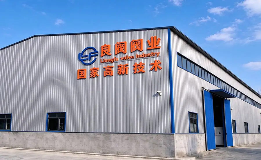
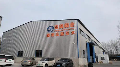
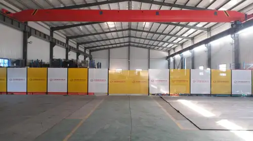
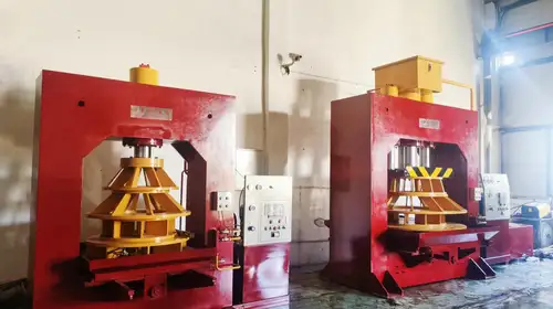
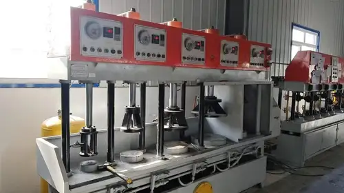
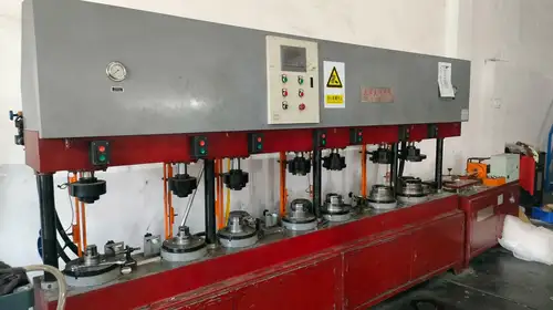
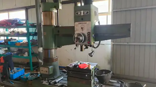
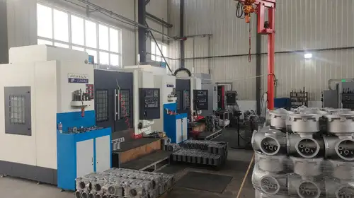
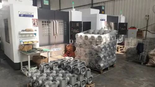
At Liangfa, our manufacturing and supply process covers mold development, casting, precision machining, coating, assembly and export packing. We can provide product drawings, technical parameters and material-selection support to help customers review the semi-lug butterfly valve against their piping requirements.
According to the project and order requirements, we can arrange factory inspection documentation and applicable material test records. Our service includes pre-sales selection assistance, production updates, export documents, spare-parts supply and remote installation guidance. The source service terms state a response to quality feedback within 24 working hours and a 12-month warranty from shipment; the applicable terms should be confirmed in the sales contract.
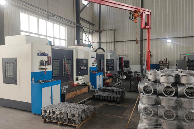
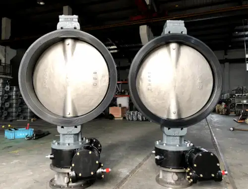
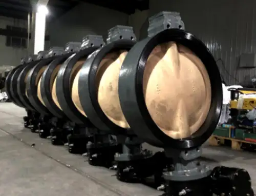
Factory Tour
Our production and inspection workflow supports the manufacture and preparation of industrial valves for shipment.
Packing and Shipping
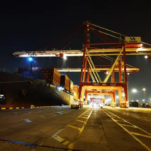
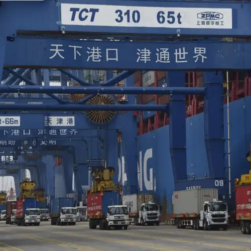
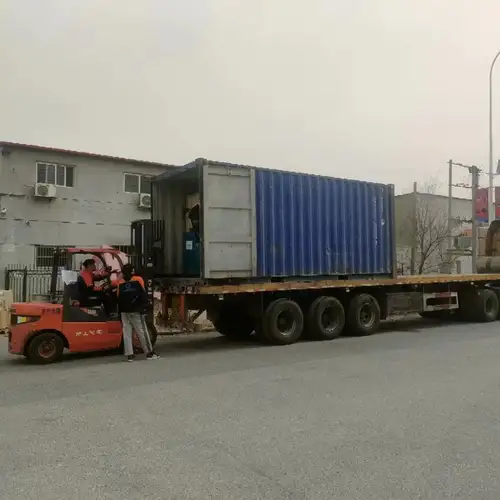
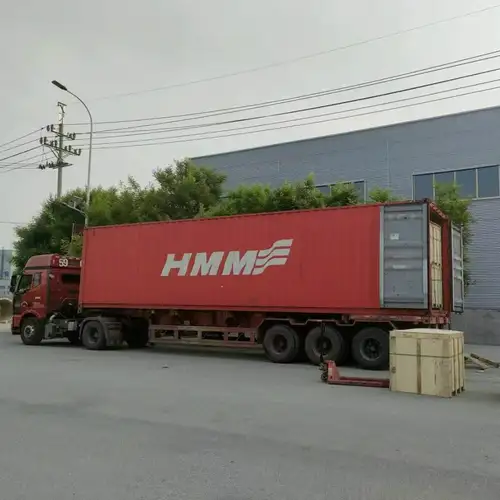
We provide export packing and arrange sea or land transport according to order requirements. Packaging and shipping details can be coordinated based on valve size, quantity, destination and handling requirements.
Application Gallery
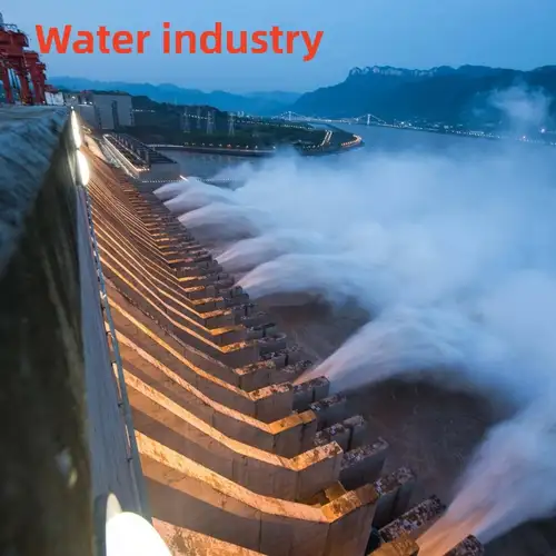
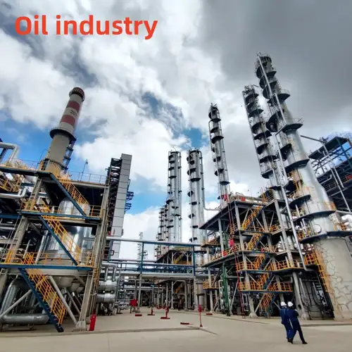
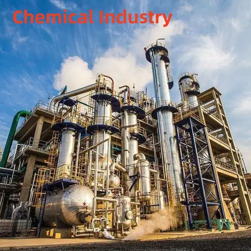
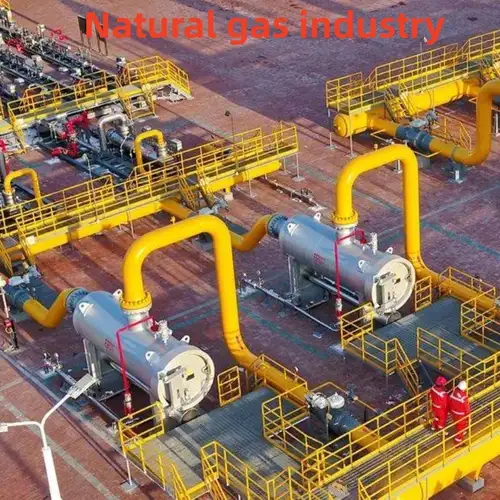
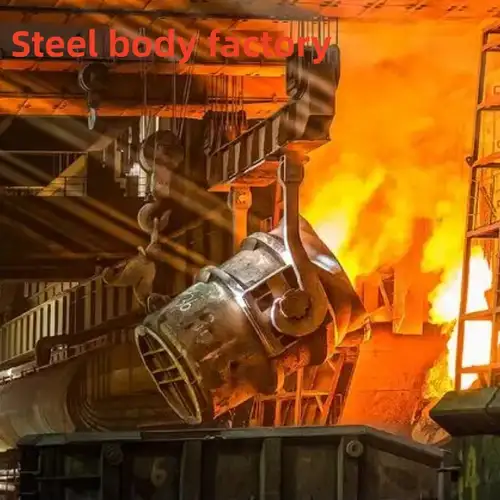
The following images illustrate application environments and product-use scenarios supplied with the original material.

Frequently Asked Questions
How is the correct side identified during installation?
Identify the side with threaded lugs and connect it to the pump or equipment flange. The opposite wafer side connects to the pipeline. Confirm the body markings and approved installation drawing before fitting the valve.
Can the semi-lug butterfly valve be used for blind-end isolation?
Only the threaded-lug side is intended to withstand blind-end pressure within the confirmed rating. The wafer side must not be used for blind-end pressure isolation. Where isolation is required on both sides, consider a full-lug design or another approved solution.
Which seat should I choose for diesel or lubricating oil?
NBR is a common option for compatible oil-based media within its specified temperature range. EPDM should not be used with oil products. Please provide the fluid type, additives and operating temperature so the seat can be checked for compatibility.
Can the valve be supplied for seawater service?
Material selection is essential for seawater. The source guide identifies 316L stainless steel and aluminium bronze options for relevant marine conditions and warns against long-term use of SS304 in seawater. The complete wetted-material combination and any project approval requirements should be confirmed before ordering.
What information is needed for a quotation?
Please provide the nominal diameter, pressure rating, medium, operating temperature, body and disc material requirements, seat preference, connection standard, actuator type and quantity. If the valve will be installed at a pump outlet or pipe end, also describe the required isolation arrangement.
Can replacement parts be supplied?
Yes. We can discuss the supply of replacement seats, handles, discs and other applicable parts. Please provide the model, size, material configuration and, where available, the original order or valve identification details to help us confirm compatibility.
Send Inquiry
Contact Info
-
Address
No. 2 Taikang Road, Xiditou Town, Beichen District, Tianjin City, China
-
Tel
-
Email
If you have any inquiry about a quotation or cooperation, please feel free to email or use the following inquiry form. Our sales representative will contact you within 24 hours.
Related Products
News Recommendations